Double Pipe
The double-pipe heat exchanger is one of the simplest heat exchangers utilized in industry. This exchanger’s name comes from how one fluid flows inside a pipe and the other fluid flows between that pipe and another pipe that surrounds the first, essentially a “tube within a tube.” One way to improve heat transfer is to add fins on the outside of the inner tube. This is used to improve the heat transfer of a fluid with a low heat transfer coefficient such as a viscous liquid or a gas, which is passed on the outer side.
There are two flow configurations that can be used using a double pipe heat exchanger. These are co-current flow and counter current flow.
Co-Current Flow
In co-current flow, also known as parallel flow, the two fluids that are exchanging heat are flowing in the same direction. Co-current flow is generally employed when there is less heat transfer required, as this method has a lower heat transfer coefficient. However, this flow is used much less than counter-current flow in industry, as this method is not as efficient given the capital costs used in purchasing the equipment (Mecklenburgh, 1985).
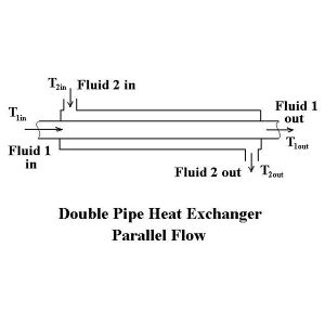
Figure 3: Double Pipe Parallel Flow (Encyclopedia.org)
Counter-Current Flow
The counter current flow mechanism is used for condensing, gas cooling, and liquid-liquid applications. Here, the fluids flow against each other in opposite directions. In the industry, counter current movement is used more often, as there is a higher rate of heat transfer. This method maximizes the temperature differences between the tube side and shell side fluids, resulting in more heat transfer and less surface area given a constant duty.
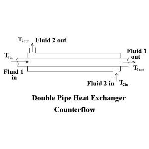
Figure 4 : Double Pipe Counter-Current Flow (Encyclopedia.org)
Table 1: Advantages and Disadvantages of Double Pipe Heat Exchangers (Leung, 2015).
| Advantages | Disadvantages |
|---|---|
| Simple to operate | Higher duties see a significant increase in pricing |
| Relatively simple structure with large amount of heat transfer | Inspection of shell side of the tubes for damage is difficult |
| Easy to maintain and repair if damaged or fouling residue incurs | Having only two single flow areas leads to low fluid flow rates |
| Suppliers easily found globally | |
| High pressure and temperatures are withstanded |
Applications
Double pipe heat exchangers can withstand high pressures and temperature. They also do not have high surface area requirements, making them economically feasible for many different applications. Double pipe heat exchangers are also used where abrasive materials are present, smaller duties, and high fouling applications, such as slurries. A more common configuration of the double pipe is with modular U-tubes in a “hairpin” configuration to conserve space. Double pipe heat exchangers have lower efficiencies compared to other heat exchangers such as the shell and tube, which has led to a decline in use in industry. However, the simplicity of the double pipe heat exchanger allows its design to be studied by students much easier, and is generally the first kind of heat exchanger introduced to a student studying heat transfer.
Shell-and-Tube
A bundle of tubes is passed through a shell. Heat exchange occurs between the fluid inside the tubes (tube-side) and the fluid outside of the tubes but within the shell (shell-side). Baffles are often used to direct the flow of the shell-side fluids as well as to support the tube bundle. TEMA has set standards for construction of shell-and-tube heat exchangers as well as nomenclature for the front heads (4 types), shells (6 types), and rear heads (8 types) (Towler and Sinnott, 2013).
Three commonly used types of shell-and-tube heat exchangers are: the fixed-tube, U-tube, and floating-head type. Each has its own set of advantages and disadvantages. For example, the fixed-tube type exchanger has the simplest construction, which reduces construction cost and difficulty of routine cleaning. However, it may not be the most efficient. Meanwhile, the U-tube configuration allows more surface area inside the exchanger, but is more difficult to clean. Additionally, the flow pattern is not truly a counterflow pattern unless a longitudinal baffle is used (Type F shell). The U-tube configuration is more able to absorb the stress of thermal expansion than the fixed tube exchanger. Finally, the floating¬-head exchanger can move within the shell, which allows the exchanger to handle higher temperatures and pressures. However, it is more complex than the former two types, and thus construction can be approximately 25 percent higher for a unit of similar area (Peters et al., 2002).
The tube pitch describes the center-to-center distance for the arrangement of the tube bundle, and can be square or triangular. A larger pitch leaves more space between tubes and allows for easier cleaning, but this comes at the cost of a lower shell-side heat transfer coefficient and the need for a larger shell. A smaller pitch allows more tubes to be fit inside a given shell.
Triangular pitch allows for tighter packing of tubes in a shell. If shell-side fouling is a problem, square pitch should be used for easier cleaning. In horizontal boiling heat exchangers, square pitch should also be used to prevent vapor blanketing. Square pitch should also be used when there is a lower shell-side pressure drop (Towler and Sinnott, 2013).
The baffles lead to increased pressure drop of the shell-side fluid. However, it also improves the mixing of the fluid and increases turbulence, which leads to improved heat transfer. Again, the tradeoff between improved heat transfer and pressures drop is illustrated. The most common type of baffle is the segmental baffle. Other baffles include the disk-and-doughnut, orifice, no-tube-in-window, and triple segmental baffle.
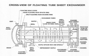
Figure 5: Shell and Tube Heat Exchanger (regonline.com)
Scraped-Surface
Crystallization systems and heat transfer involving viscous fluids, fouling may occur rapidly enough to make routine cleaning impractical. In this case, a rotating blade moves over the surface, liberating the deposited material from the surface and allowing it to exit at the bottom of the exchanger. Additionally, the motion of the blade shears the deposited product close to the wall, which results in high local heat transfer rates. Scraped-surface exchangers are generally not considered unless liquid viscosity exceeds 1 Pa•s or fouling is rapid.

Figure 6 : Scraped-Surface Heat Exchanger (regonline.com)
Gasketed and Welded Plate
Plate heat exchangers consist of a stack of corrugated plates. The corrugation of the plates improves rigidity, controls spacing of the plates, and increases the heat-transfer area compared to a flat plate.The hot and cold streams flow countercurrently through the alternating spaces created by the plates. The modular design allows easy addition of more heat transfer area, but at a cost of increased pressure drop. Edges can be sealed with gaskets for lower pressures. Cleaning is relatively simple because the configuration can be disassembled and cleaned. For operating at higher pressures the edges can be welded. Welded-plate heat exchangers typically do not operate past 3 MPa. However, in welding the plates together, the convenience of disassembling and cleaning the modular plates is lost, and cleaning must be done chemically. Additionally, the plates are usually larger than those of the gasketed-plate exchanger to reduce the amount of welding necessary.
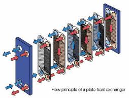
Figure 7 : Gasketed-Plate Heat Exchanger (wassertech.com)
Spiral Plate and Tube
Spiral plates are coiled to create alternating passages for the fluids. The cold fluid enters at the periphery and flows towards the center, while the hot fluid enters at the center and flows outward. Introducing the cold fluid at the periphery reduces or eliminates the need for external insulation. These heat exchangers are used for small capacities with viscous, fouling, and corrosive fluids. The end plates can be removed for cleaning the shell. However, the configuration of the tube makes the spiral plates difficult to clean.
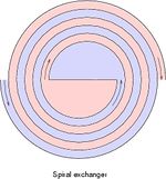
Figure 8 : Spiral Plate and Tube Heat Exchanger (regonline.com)
Plate-Fin
Plate-fin heat exchangers consist of layers of corrugated metallic sheets (fins) between flat plates to form the flow passages. The plates are sealed with metal bars on the side. Plate-fin heat exchangers can be 9 times as compact as a shell-and-tube heat exchanger, and weighs less. Can withstand design pressures up to 6 MPa in the temperature range of -270 and 800 ⁰C. Many different configurations of plate-fin exchangers can be used.
Plate
Plate heat exchangers utilize metal plates to perform heat transfer between two fluids. They are composed of a lot of thin metal plates compressed together by two pressure plates into a “plate pack.” Fluid paths within a plate heat exchanger alternate between the plates, allowing the fluids to transfer heat in a small area without mixing. Plates are generally corrugated in order to increase the heat transfer area (surface area) and turbulence, and thus maximize the amount of heat transfer completed. Plate heat exchangers expose fluids to a larger surface area compared to a conventional heat exchanger such as a double pipe or a shell and tube. The fluids are spread out over the plates, increasing the rate of temperature change significantly. There are four types of plate heat exchangers: brazed plate, welded, semi-welded, and gasketed.
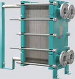
Figure 9 : Plate heat exchangers (heat-exchangers.com)
Gasketed Plate
Gasketed plate exchangers use high quality gaskets to seal plates together and protect against leakage. Maintenance and repairing costs are generally low due to the simplicity of removing the plates. Additionally, gasketed plate heat exchangers allow for increased flexibility in industrial settings, as plates can be added and removed easily to increase or decrease heat transfer as necessary (useful if fouled). Also, plates of the same type can be used in heat exchangers of the same size, so one set of backup plates can be used in all heat exchangers of the same size. Common industrial applications of this type of heat exchanger include HVAC, pharmaceutical, and dairy.
Brazed Plate
Brazed plate exchangers are generally used in refrigeration applications. They are highly resistant to corrosion due to its copper brazing and stainless steel plate composition.
Welded Plate
Welded plate exchangers have plates that are welded together, making them extremely durable and ideal for high temperatures and corrosive material. However, mechanical cleaning of plates is not an option due to the plates being welded together, so maintenance and repairing costs will be significantly higher. Common industrial applications that use this type of plate heat exchanger include hazardous liquids, process chemicals, and oil cooling.
Semi-Welded
Semi-welded exchangers show a mixture of the welded and gasketed plates. Pairs of two plates are welded together, and gasketed to other pairs of plates. Thus, one fluid path is welded while the other path is gasketed. A benefit of having this type of exchanger is that it is able to transfer more corrosive and high temperature fluids, while having the accessibility of cleaning the plates relatively easily. There is also a very low risk of fluid loss with this type of exchanger, and thus, it is recommended to use this type of heat exchanger when transferring materials that are expensive.
There are certain limitations to plate heat exchangers. Heat transfer between two liquids of large temperature differences are not very efficient, and it is generally better to use a shell and tube heat exchanger instead. There is also a possibility of high pressure loss due to turbulence created from the narrow flow channels, so applications requiring low pressure loss should not be considered (Towler and Sinnott, 2013).
Design Considerations for Plate Heat Exchangers
As with any heat exchanger type, there are several important design factors to consider when designing a plate-and-frame heat exchanger. These factors include temperature approach, pressure drop, number of passes, channel velocity, plate gap, and plate thickness, and corrugation arrangement.
The most important factor is temperature approach. Approach temperature capabilities are better than shell-and-tube heat exchangers, with minimum approach temperatures of 1-3 F. However, it is important to note that smaller approach temperatures necessitate more plates – and thus increase cost. If the freedom to choose approach temperature exists, approach temperatures of 5-10 F are ideal for design.
Pressure drop is an important consideration, as smaller gaps in the heat exchanger result in higher pressure drops than other exchangers. Generally, the pressure drop increases with number of plates and flow rate through the exchanger, while decreasing with an increase in number of passes.
As with shell-and-tube heat exchangers, increasing number of passes decreases the pressure drop in the exchanger, allowing for the addition of heat transfer area without reaching maximum pressure drop. When considering increasing the number of passes, plate heat exchangers allow for flexibility. Odd number of passes must have opposite inlet and outlet connections, and even number passes must have same side inlet and outlet connections. However, adding another two passes only requires the addition of two “turn plates” – which are plates lacking holes on the side which is being passed.
Channel velocities are important to reduce fouling between plates. Since there is a small gap between plates, a small amount of fouling can significantly reduce heat transfer. Although increasing plate gap can lengthen the amount of time between cleanings, increasing channel velocity allows a small gap to be retained, while still increasing time between cleanings. However, channel velocities that are too high can increase the risk for a blowout. For most design applications, 1-2 ft/s allow for reduced fouling while ensuring safe operation (Peters et al., 2002).
Example of a high-theta plate (left) and a low-theta plate (right)
Plate gap is exactly as it sounds – the gap between two plates. Typical gaps between plates range from 1.3 – 1.5 mm. Increasing the gap between plates reduces velocity and decreases pressure drop, but decreases heat transfer as there is more fluid that does not contact either side of the plate. Plate gap can be adjusted in industry by tightening or loosening the end bolts on the heat exchanger – although overtightening can lead to crushing, and undertightening can result in leaks.
As with plate gap, increasing plate thickness decreases heat transfer. From heat transfer, a greater wall thickness increases resistance to heat transfer. However, when working with abrasive or corrosive fluids, thicker plates can be necessary for safety purposes.
Finally, chevron arrangement affects heat transfer. Each manufacturer configures corrugation patterns differently, with some companies offering multiple styles. In general, however, increasing the chevron angle decreases the heat transfer and the pressure drop. Therefore, altering chevron angle is another way use the trade off between heat transfer and pressure drop limitations. For the two plates shown on the right, the left plate has a high angle, and therefore higher heat transfer and higher pressure drop. Unfortunately, each company has a specific, proprietary arrangement and design of corrugation (Towler and Sinnott, 2013).
Gas-to-Gas
Gas-to-gas heat exchangers are primarily used to recover energy from combustion gases to preheat furnace air. The plain tube gas-to-gas heat exchanger is a simple countercurrent exchange through a tube bank, either in a single-pass (cross-flow) or multipass configuration (Peters et al., 2002).
Leave a Reply