One-Dimensional Inelastic Collision
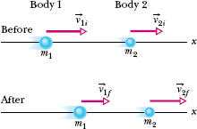
Figure 9-14 shows two bodies just before and just after they have a one-dimensional collision. The velocities before the collision (subscript i) and after the collision (subscript f) are indicated. The two bodies form our system, which is closed and isolated. We can write the law of conservation of linear momentum for this two-body system as

which we can symbolize as

Because the motion is one-dimensional, we can drop the overhead arrows for vectors and use only components along the axis. Thus, from p = mv, we can rewrite Eq. 9-50 as

If we know values for, say, the masses, the initial velocities, and one of the final velocities, we can find the other final velocity with Eq. 9-51.

Fig. 9-14 Bodies 1 and 2 move along an x axis, before and after they have an inelastic collision.

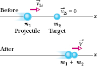
Fig. 9-15 A completely inelastic collision between two bodies. Before the collision, the body with mass m2 is at rest and the body with mass m1 moves directly toward it. After the collision, the stuck-together bodies move with the same velocity ![]() .
.
One-Dimensional Completely Inelastic Collision
Figure 9-15 shows two bodies before and after they have a completely inelastic collision (meaning they stick together). The body with mass m2 happens to be initially at rest (v2i = 0). We can refer to that body as the target and to the incoming body as the projectile. After the collision, the stuck-together bodies move with velocity V. For this situation, we can rewrite Eq. 9-51 as


If we know values for, say, the masses and the initial velocity v1i of the projectile, we can find the final velocity V with Eq. 9-53. Note that V must be less than v1i because the mass ratio m1/(m1 + m2) must be less than unity.
Velocity of the Center of Mass
In a closed, isolated system, the velocity ![]() of the center of mass of the system cannot be changed by a collision because, with the system isolated, there is no net external force to change it. To get an expression for
of the center of mass of the system cannot be changed by a collision because, with the system isolated, there is no net external force to change it. To get an expression for ![]() , let us return to the two-body system and one-dimensional collision of Fig. 9-14. From Eq. 9-25
, let us return to the two-body system and one-dimensional collision of Fig. 9-14. From Eq. 9-25 ![]() we can relate
we can relate ![]() to the total linear momentum
to the total linear momentum ![]() of that two body system by writing
of that two body system by writing

The total linear momentum ![]() is conserved during the collision; so it is given by either side of Eq. 9-50. Let us use the left side to write
is conserved during the collision; so it is given by either side of Eq. 9-50. Let us use the left side to write

Substituting this expression for ![]() in Eq. 9-54 and solving for
in Eq. 9-54 and solving for ![]() give us
give us

The right side of this equation is a constant, and ![]() has that same constant value before and after the collision.
has that same constant value before and after the collision.
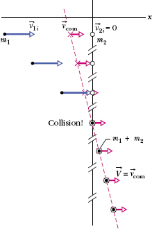
For example, Fig. 9-16 shows, in a series of freeze-frames, the motion of the center of mass for the completely inelastic collision of Fig. 9-15. Body 2 is the target, and its initial linear momentum in Eq. 9-56 is ![]() . Body 1 is the projectile, and its initial linear momentum in Eq. 9-56 is
. Body 1 is the projectile, and its initial linear momentum in Eq. 9-56 is ![]() . Note that as the series of freeze-frames progresses to and then beyond the collision, the center of mass moves at a constant velocity to the right. After the collision, the common final speed V of the bodies is equal to
. Note that as the series of freeze-frames progresses to and then beyond the collision, the center of mass moves at a constant velocity to the right. After the collision, the common final speed V of the bodies is equal to ![]() because then the center of mass travels with the stuck-together bodies.
because then the center of mass travels with the stuck-together bodies.
![]() CHECKPOINT 9 Body 1 and body 2 are in a completely inelastic one-dimensional collision. What is their final momentum if their initial momenta are, respectively, (a) 10 kg · m/s and 0; (b) 10 kg · m/s and 4 kg · m/s; (c) 10 kg · m/s and −4 kg · m/s?
CHECKPOINT 9 Body 1 and body 2 are in a completely inelastic one-dimensional collision. What is their final momentum if their initial momenta are, respectively, (a) 10 kg · m/s and 0; (b) 10 kg · m/s and 4 kg · m/s; (c) 10 kg · m/s and −4 kg · m/s?

Fig. 9-16 Some freeze-frames of the two-body system in Fig. 9-15, which undergoes a completely in-elastic collision. The system’s center of mass is shown in each freeze-frame. The velocity ![]() of the center of mass is unaffected by the collision. Because the bodies stick together after the collision, their common velocity
of the center of mass is unaffected by the collision. Because the bodies stick together after the collision, their common velocity ![]() must be equal to
must be equal to ![]() .
.
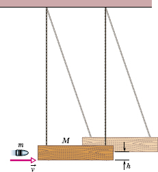
The ballistic pendulum was used to measure the speeds of bullets before electronic timing devices were developed. The version shown in Fig. 9-17 consists of a large block of wood of mass M = 5.4 kg, hanging from two long cords. A bullet of mass m = 9.5 g is fired into the block, coming quickly to rest. The block + bullet then swing upward, their center of mass rising a vertical distance h = 6.3 cm before the pendulum comes momentarily to rest at the end of its arc. What is the speed of the bullet just prior to the collision?
Solution: We can see that the bullet’s speed v must determine the rise height h. However, a Key Idea is that we cannot use the conservation of mechanical energy to relate these two quantities because surely energy is transferred from mechanical energy to other forms (such as thermal energy and energy to break apart the wood) as the bullet penetrates the block. Another Key Idea helps—we can split this complicated motion into two steps that we can separately analyze: (1) the bullet–block collision and (2) the bullet–block rise, during which mechanical energy is conserved.
Step 1 Because the collision within the bullet–block system is so brief, we can make two important assumptions: (1) During the collision, the gravitational force on the block and the force on the block from the cords are still balanced. Thus, during the collision, the net external impulse on the bullet–block system is zero. Therefore, the system is isolated and its total linear momentum is conserved. (2) The collision is one-dimensional in the sense that the direction of the bullet and block just after the collision is in the bullet’s original direction of motion.
Because the collision is one-dimensional, the block is initially at rest, and the bullet sticks in the block, we use Eq. 9-53 to express the conservation of linear momentum. Replacing the symbols there with the corresponding symbols here, we have

Step 2 As the bullet and block now swing up together, the mechanical energy of the bullet–block–Earth system is conserved. (This mechanical energy is not changed by the force of the cords on the block, because that force is always directed perpendicular to the block’s direction of travel.) Let’s take the block’s initial level as our reference level of zero gravitational potential energy. Then conservation of mechanical energy means that the system’s kinetic energy at the start of the swing must equal its gravitational potential energy at the highest point of the swing. Because the speed of the bullet and block at the start of the swing is the speed V immediately after the collision, we may write this conservation as swing. Because the speed of the bullet and block at the start of the swing is the speed V immediately after the collision, we may write this conservation as

Fig. 9-17 A ballistic pendulum, used to measure the speeds of bullets.

Substituting for V from Eq. 9-57 leads to

The ballistic pendulum is a kind of “transformer,” exchanging the high speed of a light object (the bullet) for the low—and thus more easily measurable—speed of a massive object (the block).
Figure 9-18 represents two identical cars about to collide head-on in a completely inelastic, one-dimensional collision along an x axis. During the collision, the two cars form a closed system. Let’s make the reasonable assumption that during the collision the impulse between the cars is so great that we can neglect the relatively minor impulses due to the frictional forces on the tires from the road. Then we can assume that there is no net external force on the two-car system.
The x component of the initial velocity of car 1 along the x axis is v1i = +25 m/s, and that of car 2 is v2i = −25 m/s. During the collision, the force (and thus the impulse) on each car causes a change Δv in the car’s velocity. The probability of a driver being killed depends on the magnitude of Δv for that driver’s car. We want to calculate the changes Δv1 and Δv2 in the velocities of the two cars.
(a) First, let each car carry only a driver. The total mass of car 1 (including driver 1) is m1 = 1400 kg, and the total mass of car 2 (including driver 2) is m2 = 1400 kg. What are the changes Δv1 and Δv2 in the velocities of the cars?

Fig. 9-18 Two cars about to collide head-on.
Solution: The Key Idea here is that because the system is closed and isolated, its total linear momentum is conserved. From Eq. 9-51, we can write this fact as

Since the collision is completely inelastic, the two cars stick together and thus have the same velocity V after the collision. Substituting V for v1f and v2f into Eq. 9-58 and solving for V, we have

Substitution of the given data then results in

Thus, the change in the velocity of car 1 is

and the change in the velocity of car 2 is

(b) Next, we reconsider the collision, but this time with an 80 kg passenger in car 1. What are Δv1 and Δv2 now?
Solution: We have the same Key Idea as before. Repeating our steps but now substituting m1 = 1480 kg, we find that

(c) The magnitude of Δv1 is less with the passenger in the car. Because the probability of a driver being killed depends on Δv1, we can reason that the probability is less for driver 1.
The data on head-on car collisions do not include values of Δv, but they do include the car masses and whether or not a collision was fatal. Fitting a function to the collected data, researchers have found that the fatality risk r1 of driver 1 is given by

where c is a constant. Justify why the ratio m2/m1 appears in this equation, and then use the equation to compare the fatality risks for driver 1 with and without the passenger.
Solution: The Key Idea here is still that linear momentum is conserved in the collision, as given in Eq. 9-58. We can rewrite that equation as

Substituting Δv1 = v1f − v1i and Δv2 = v2f − v2i and rear-ranging give us

A driver’s fatality risk depends on the change Δv for that driver. In Eq. 9-61, we see that the ratio of Δv values in a collision is the inverse of the ratio of the masses, and this is the reason researchers can link fatality risk to the ratio of masses in Eq. 9-60.
From part (a) and Eq. 9-60, without the passenger, driver 1 has a fatality risk of

From part (b) and Eq. 9-60, with the passenger, driver 1 has a fatality risk of

Substituting for c from Eq. 9-62, we find

In words, the fatality risk for driver 1 is about 9% less when a passenger is in the car. (Unfortunately, as you can show, the fatality risk for driver 2 is more when a passenger is in car 1.)
Leave a Reply