Once again we consider a particle that is part of a system in which a conservative force acts. This time suppose that the particle is constrained to move along an x axis while the conservative force does work on it. We can learn a lot about the motion of the particle from a plot of the system’s potential energy U(x). However, before we discuss such plots, we need one more relationship.
Finding the Force Analytically
Equation 8-6 tells us how to find the change ΔU in potential energy between two points in a one-dimensional situation if we know the force F(x). Now we want to go the other way; that is, we know the potential energy function U(x) and want to find the force.
For one-dimensional motion, the work W done by a force that acts on a particle as the particle moves through a distance Δx is F(x) Δx. We can then write Eq. 8-1 as
ΔU(x) = − W = − F(x) Δx.
Solving for F(x) and passing to the differential limit yield

which is the relation we sought.
We can check this result by putting ![]() , which is the elastic potential energy function for a spring force. Equation 8-22 then yields, as expected, F(x) = − kx, which is Hooke’s law. Similarly, we can substitute U(x) = mgx, which is the gravitational potential energy function for a particle – Earth system, with a particle of mass m at height x above Earth’s surface. Equation 8-22 then yields F = −mg, which is the gravitational force on the particle.
, which is the elastic potential energy function for a spring force. Equation 8-22 then yields, as expected, F(x) = − kx, which is Hooke’s law. Similarly, we can substitute U(x) = mgx, which is the gravitational potential energy function for a particle – Earth system, with a particle of mass m at height x above Earth’s surface. Equation 8-22 then yields F = −mg, which is the gravitational force on the particle.
The Potential Energy Curve
Figure 8-10a is a plot of a potential energy function U(x) for a system in which a particle is in one-dimensional motion while a conservative force F(x) does work on it. We can easily find F(x) by (graphically) taking the slope of the U(x) curve at various points. (Equation 8-22 tells us that F(x) is the negative of the slope of the U(x) curve.) Figure 8-10b is a plot of F(x) found in this way.
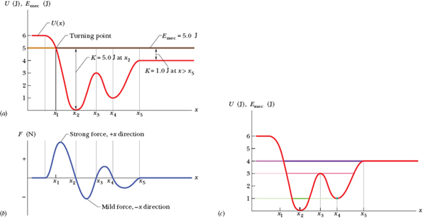
Fig. 8-10 (a) A plot of U(x), the potential energy function of a system containing a particle confined to move along an x axis. There is no friction, so mechanical energy is conserved. (b) A plot of the force F(x) acting on the particle, derived from the potential energy plot by taking its slope at various points. (c) The U(x) plot of (a) with three possible values of Emec shown.
Turning Points
In the absence of a nonconservative force, the mechanical energy E of a system has a constant value given by

Here K(x) is the kinetic energy function of a particle in the system (this K(x) gives the kinetic energy as a function of the particle’s location x). We may rewrite Eq. 8-23 as

Suppose that Emec (which has a constant value, remember) happens to be 5.0 J. It would be represented in Fig. 8-10a by a horizontal line that runs through the value 5.0 J on the energy axis. (It is, in fact, shown there.)
Equation 8-24 tells us how to determine the kinetic energy K for any location x of the particle: On the U(x) curve, find U for that location x and then subtract U from Emec. For example, if the particle is at any point to the right of x5, then K = 1.0 J. The value of K is greatest (5.0 J) when the particle is at x2 and least (0 J) when the particle is at x1.
Since K can never be negative (because v2 is always positive), the particle can never move to the left of x1, where Emec − U is negative. Instead, as the particle moves toward x1 from x2, K decreases (the particle slows) until K = 0 at x1 (the particle stops there).
Note that when the particle reaches x1, the force on the particle, given by Eq. 8-22, is positive (because the slope dU/dx is negative). This means that the particle does not remain at x1 but instead begins to move to the right, opposite its earlier motion. Hence x1 is a turning point, a place where K = 0 (because U = E) and the particle changes direction. There is no turning point (where K = 0) on the right side of the graph. When the particle heads to the right, it will continue indefinitely.
Equilibrium Points
Figure 8-10c shows three different values for Emec superposed on the plot of the potential energy function U(x) of Fig. 8-10a. Let us see how they change the situation. If Emec = 4.0 J (purple line), the turning point shifts from x1 to a point between x1 and x2. Also, at any point to the right of x5, the system’s mechanical energy is equal to its potential energy; thus, the particle has no kinetic energy and (by Eq. 8-22) no force acts on it, and so it must be stationary. A particle at such a position is said to be in neutral equilibrium. (A marble placed on a horizontal tabletop is in that state.)
If Emec = 3.0 J (pink line), there are two turning points: One is between x1 and x2, and the other is between x4 and x5. In addition, x3 is a point at which K = 0. If the particle is located exactly there, the force on it is also zero, and the particle remains stationary. However, if it is displaced even slightly in either direction, a nonzero force pushes it farther in the same direction, and the particle continues to move. A particle at such a position is said to be in unstable equilibrium. (A marble balanced on top of a bowling ball is an example.)
Next consider the particle’s behavior if Emec = 1.0 J (green line). If we place it at x4, it is stuck there. It cannot move left or right on its own because to do so would require a negative kinetic energy. If we push it slightly left or right, a restoring force appears that moves it back to x4. A particle at such a position is said to be in stable equilibrium. (A marble placed at the bottom of a hemispherical bowl is an example.) If we place the particle in the cup-like potential well centered at x2, it is between two turning points. It can still move somewhat, but only partway to x1 or x3.
![]() CHECKPOINT 4 The figure gives the potential energy function U(x) for a system in which a particle is in one-dimensional motion. (a) Rank regions AB, BC, and CD according to the magnitude of the force on the particle, greatest first. (b) What is the direction of the force when the particle is in region AB?
CHECKPOINT 4 The figure gives the potential energy function U(x) for a system in which a particle is in one-dimensional motion. (a) Rank regions AB, BC, and CD according to the magnitude of the force on the particle, greatest first. (b) What is the direction of the force when the particle is in region AB?

8-7 Work Done on a System by an External Force
In Chapter 7, we defined work as being energy transferred to or from an object by means of a force acting on the object. We can now extend that definition to an external force acting on a system of objects.
![]() Work is energy transferred to or from a system by means of an external force acting on that system.
Work is energy transferred to or from a system by means of an external force acting on that system.
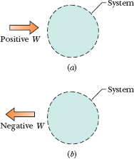
Fig. 8-11 (a) Positive work W done on an arbitrary system means a transfer of energy to the system. (b) Negative work W means a transfer of energy from the system.
Figure 8-11a represents positive work (a transfer of energy to a system), and Fig. 8-11b represents negative work (a transfer of energy from a system). When more than one force acts on a system, their net work is the energy transferred to or from the system.
These transfers are like transfers of money to and from a bank account. If a system consists of a single particle or particle-like object, as in Chapter 7, the work done on the system by a force can change only the kinetic energy of the system. The energy statement for such transfers is the work–kinetic energy theorem of Eq. 7-10 (ΔK = W); that is, a single particle has only one energy account, called kinetic energy. External forces can transfer energy into or out of that account. If a system is more complicated, however, an external force can change other forms of energy (such as potential energy); that is, a more complicated system can have multiple energy accounts.
Let us find energy statements for such systems by examining two basic situations, one that does not involve friction and one that does.
No Friction Involved
To compete in a bowling-ball-hurling contest, you first squat and cup your hands under the ball on the floor. Then you rapidly straighten up while also pulling your hands up sharply, launching the ball upward at about face level. During your upward motion, your applied force on the ball obviously does work; that is, it is an external force that transfers energy, but to what system?
To answer, we check to see which energies change. There is a change ΔK in the ball’s kinetic energy and, because the ball and Earth become more separated, there is a change ΔU in the gravitational potential energy of the ball–Earth system. To include both changes, we need to consider the ball–Earth system. Then your force is an external force doing work on that system, and the work is


where ΔEmec is the change in the mechanical energy of the system. These two equations, which are represented in Fig. 8-12, are equivalent energy statements for work done on a system by an external force when friction is not involved.
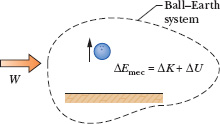
Fig. 8-12 Positive work W is done on a system of a bowling ball and Earth, causing a change ΔEmec in the mechanical energy of the system, a change ΔK in the ball’s kinetic energy, and a change ΔU in the system’s gravitational potential energy.
Friction Involved
We next consider the example in Fig. 8-13a. A constant horizontal force ![]() pulls a block along an x axis and through a displacement of magnitude d, increasing the block’s velocity from
pulls a block along an x axis and through a displacement of magnitude d, increasing the block’s velocity from ![]() to
to ![]() . During the motion, a constant kinetic frictional force
. During the motion, a constant kinetic frictional force ![]() from the floor acts on the block. Let us first choose the block as our system and apply Newton’s second law to it. We can write that law for components along the x axis (Fnet,x = max) as
from the floor acts on the block. Let us first choose the block as our system and apply Newton’s second law to it. We can write that law for components along the x axis (Fnet,x = max) as

Because the forces are constant, the acceleration ![]() is also constant. Thus, we can use Eq. 2-16 to write
is also constant. Thus, we can use Eq. 2-16 to write

Solving this equation for a, substituting the result into Eq. 8-27, and rearranging then give us

or, because ![]() for the block,
for the block,

In a more general situation (say, one in which the block is moving up a ramp), there can be a change in potential energy. To include such a possible change, we generalize Eq. 8-29 by writing

By experiment we find that the block and the portion of the floor along which it slides become warmer as the block slides. As we shall discuss in Chapter 18, the temperature of an object is related to the object’s thermal energy Eth (the energy associated with the random motion of the atoms and molecules in the object). Here, the thermal energy of the block and floor increases because (1) there is friction between them and (2) there is sliding. Recall that friction is due to the cold-welding between two surfaces. As the block slides over the floor, the sliding causes repeated tearing and reforming of the welds between the block and the floor, which makes the block and floor warmer. Thus, the sliding increases their thermal energy Eth.
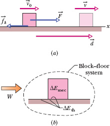
Fig. 8-13 (a) A block is pulled across a floor by force ![]() while a kinetic frictional force
while a kinetic frictional force ![]() opposes the motion. The block has velocity
opposes the motion. The block has velocity ![]() at the start of a displacement
at the start of a displacement ![]() and velocity
and velocity ![]() at the end of the displacement. (b) Positive work W is done on the block–floor system by force
at the end of the displacement. (b) Positive work W is done on the block–floor system by force ![]() , resulting in a change ΔEmec in the block’s mechanical energy and a change ΔEth in the thermal energy of the block and floor.
, resulting in a change ΔEmec in the block’s mechanical energy and a change ΔEth in the thermal energy of the block and floor.
Through experiment, we find that the increase ΔEth in thermal energy is equal to the product of the magnitudes fk and d:

Thus, we can rewrite Eq. 8-30 as

Fd is the work W done by the external force ![]() (the energy transferred by the force), but on which system is the work done (where are the energy transfers made)? To answer, we check to see which energies change. The block’s mechanical energy changes, and the thermal energies of the block and floor also change. Therefore, the work done by force
(the energy transferred by the force), but on which system is the work done (where are the energy transfers made)? To answer, we check to see which energies change. The block’s mechanical energy changes, and the thermal energies of the block and floor also change. Therefore, the work done by force ![]() is done on the block–floor system. That work is
is done on the block–floor system. That work is

This equation, which is represented in Fig. 8-13b, is the energy statement for the work done on a system by an external force when friction is involved.
![]() CHECKPOINT 5 In three trials, a block is pushed by a horizontal applied force across a floor that is not frictionless, as in Fig. 8-13a. The magnitudes F of the applied force and the results of the pushing on the block’s speed are given in the table. In all three trials, the block is pushed through the same distance d. Rank the three trials according to the change in the thermal energy of the block and floor that occurs in that distance d, greatest first.
CHECKPOINT 5 In three trials, a block is pushed by a horizontal applied force across a floor that is not frictionless, as in Fig. 8-13a. The magnitudes F of the applied force and the results of the pushing on the block’s speed are given in the table. In all three trials, the block is pushed through the same distance d. Rank the three trials according to the change in the thermal energy of the block and floor that occurs in that distance d, greatest first.

The prehistoric people of Easter Island carved hundreds of gigantic stone statues in a quarry and then moved them to sites all over the island (Fig. 8-14). How they managed to move the statues by as much as 10 km without the use of sophisticated machines has been hotly debated. They most likely cradled each statue in a wooden sled and then pulled the sled over a “runway” consisting of almost identical logs acting as rollers. In a modern reenactment of this technique, 25 men were able to move a 9000 kg Easter Island-type statue 45 m over level ground in 2 min.
(a) Estimate the work the net force ![]() from the men did during the 45 m displacement of the statue, and determine the system on which that force did the work.
from the men did during the 45 m displacement of the statue, and determine the system on which that force did the work.
Solution: One Key Idea is that we can calculate the work done with Eq. 7-7 (W = Fd cos ![]() ). Here d is the distance 45 m, F is the magnitude of the net force on the statue from the 25 men, and
). Here d is the distance 45 m, F is the magnitude of the net force on the statue from the 25 men, and ![]() = 0°. Let us estimate that each man pulled with a force magnitude equal to twice his weight, which we take to be the same value mg for all the men. Thus, the magnitude of the net force was F = (25)(2mg) = 50mg. Estimating a man’s mass as 80 kg, we can then write Eq. 7-7 as
= 0°. Let us estimate that each man pulled with a force magnitude equal to twice his weight, which we take to be the same value mg for all the men. Thus, the magnitude of the net force was F = (25)(2mg) = 50mg. Estimating a man’s mass as 80 kg, we can then write Eq. 7-7 as

The Key Idea in determining the system on which the work is done is to see which energies change. Because the statue moved, there was certainly a change ΔK in its kinetic energy during the motion. We can easily guess that there must have been considerable kinetic friction between the sled, logs, and ground, resulting in a change ΔEth in their thermal energies. Thus, the system on which the work was done consisted of the statue, sled, logs, and ground.
(b) What was the increase ΔEth in the thermal energy of the system during the 45 m displacement?
Solution: The Key Idea here is that we can relate ΔEth to the work W done by ![]() with the energy statement of Eq. 8-33 for a system that involves friction:
with the energy statement of Eq. 8-33 for a system that involves friction:

Fig. 8-14 Easter Island stone statue.
W = ΔEmec + ΔEth.
We know the value of W from (a). The change ΔEmec in the statue’s mechanical energy was zero because the statue was stationary at the beginning and the end of the move and its elevation did not change. Thus, we find
ΔEth = W = 1.8 × 10⁶ J ≈ 2 MJ. (Answer)
(c) Estimate the work that would have been done by the 25 men if they had moved the statue 10 km across level ground on Easter Island. Also estimate the total change ΔEth that would have occurred in the statue–sled–logs–ground system.
Solution: The Key Ideas here are the same as in (a) and (b). Thus we calculate W as in (a), but with 1 × 10⁴ m now substituted for d. Also, we again equate ΔEth to W. We get
W = ΔEth = 3.9 × 10⁸ J ≈ 400 MJ. (Answer)
This would have been a staggering amount of energy for the men to have transferred during the movement of a statue. Still, the 25 men could have moved the statue 10 km, and the required energy does not suggest some mysterious source.
A food shipper pushes a wood crate of cabbage heads (total mass m = 14 kg) across a concrete floor with a constant horizontal force ![]() of magnitude 40 N. In a straight-line displacement of magnitude d = 0.50 m, the speed of the crate decreases from v0 = 0.60 m/s to v = 0.20 m/s.
of magnitude 40 N. In a straight-line displacement of magnitude d = 0.50 m, the speed of the crate decreases from v0 = 0.60 m/s to v = 0.20 m/s.
(a) How much work is done by force ![]() , and on what system does it do the work?
, and on what system does it do the work?
Solution: One Key Idea is that Eq. 7-7 holds here: The work W done by ![]() can be calculated as
can be calculated as

The Key Idea in determining the system on which the work is done is to see which energies change. Because the crate’s speed changes, there is certainly a change ΔK in the crate’s kinetic energy. Is there friction between the floor and the crate, and thus a change in thermal energy? Note that ![]() and the crate’s velocity have the same direction. Thus, a Key Idea here is that if there is no friction, then
and the crate’s velocity have the same direction. Thus, a Key Idea here is that if there is no friction, then ![]() should be accelerating the crate to a greater speed. However, the crate is slowing, so there must be friction and a change ΔEth in thermal energy of the crate and the floor. Therefore, the system on which the work is done is the crate–floor system, because both energy changes occur in that system.
should be accelerating the crate to a greater speed. However, the crate is slowing, so there must be friction and a change ΔEth in thermal energy of the crate and the floor. Therefore, the system on which the work is done is the crate–floor system, because both energy changes occur in that system.
(b) What is the increase ΔEth in the thermal energy of the crate and floor?
Solution: The Key Idea here is that we can relate ΔEth to the work W done by ![]() with the energy statement of Eq. 8-33 for a system that involves friction:
with the energy statement of Eq. 8-33 for a system that involves friction:

We know the value of W from (a). The change ΔEmec in the crate’s mechanical energy is just the change in its kinetic energy because no potential energy changes occur, so we have

Substituting this into Eq. 8-34 and solving for ΔEth, we find

Leave a Reply