Now we are ready to analyze projectile motion, horizontally and vertically.
The Horizontal Motion
Because there is no acceleration in the horizontal direction, the horizontal component vx of the projectile’s velocity remains unchanged from its initial value v0x throughout the motion, as demonstrated in Fig. 4-13. At any time t, the projectile’s horizontal displacement x − x0 from an initial position x0 is given by Eq. 2-15 with a = 0, which we write as

Because v0x = v0 cos θ0, this becomes

The Vertical Motion
The vertical motion is the motion we discussed in Section 2-9 for a particle in free fall. Most important is that the acceleration is constant. Thus, the equations of Table 2-1 apply, provided we substitute −g for a and switch to y notation. Then, for example, Eq. 2-15 becomes

where the initial vertical velocity component v0y is replaced with the equivalent v0 sin θ0. Similarly, Eqs. 2-11 and 2-16 become


As is illustrated in Fig. 4-10 and Eq. 4-23, the vertical velocity component behaves just as for a ball thrown vertically upward. It is directed upward initially, and its magnitude steadily decreases to zero, which marks the maximum height of the path. The vertical velocity component then reverses direction, and its magnitude becomes larger with time.
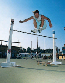
Fig. 4-13 The vertical component of this skateboarder’s velocity is changing but not the horizontal component, which matches the skateboard’s velocity. As a result, the skateboard stays underneath him, allowing him to land on it.
The Equation of the Path
We can find the equation of the projectile’s path (its trajectory) by eliminating time t between Eqs. 4-21 and 4-22. Solving Eq. 4-21 for t and substituting into Eq. 4-22, we obtain, after a little rearrangement,

This is the equation of the path shown in Fig. 4-10. In deriving it, for simplicity we let x0 = 0 and y0 = 0 in Eqs. 4-21 and 4-22, respectively. Because g, θ0, and v0 are constants, Eq. 4-25 is of the form y = ax + bx2, in which a and b are constants. This is the equation of a parabola, so the path is parabolic.
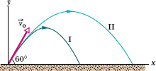
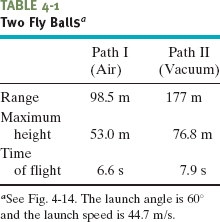
Fig. 4-14 (I) The path of a fly ball calculated by taking air resistance into account. (II) The path the ball would follow in a vacuum, calculated by the methods of this chapter. See Table 4-1 for corresponding data. (Adapted from “The Trajectory of a Fly Ball,” by Peter J. Brancazio, The Physics Teacher, January 1985.)
The Horizontal Range
The horizontal range R of the projectile, as Fig. 4-10 shows, is the horizontal distance the projectile has traveled when it returns to its initial (launch) height. To find range R, let us put x − x0 = R in Eq. 4-21 and y − y0 = 0 in Eq. 4-22, obtaining

Eliminating t between these two equations yields

Using the identity sin 2θ0 = 2 sin θ0 cos θ0 (see Appendix E), we obtain

Caution: This equation does not give the horizontal distance traveled by a projectile when the final height is not the launch height.
Note that R in Eq. 4-26 has its maximum value when sin 2θ0 = 1, which corresponds to 2θ0 = 90° or θ0 = 45°.
![]() The horizontal range R is maximum for a launch angle of 45°.
The horizontal range R is maximum for a launch angle of 45°.
The Effects of the Air
We have assumed that the air through which the projectile moves has no effect on its motion. However, in many situations, the disagreement between our calculations and the actual motion of the projectile can be large because the air resists (opposes) the motion. Figure 4-14, for example, shows two paths for a fly ball that leaves the bat at an angle of 60° with the horizontal and an initial speed of 44.7 m/s. Path I (the baseball player’s fly ball) is a calculated path that approximates normal conditions of play, in air. Path II (the physics professor’s fly ball) is the path the ball would follow in a vacuum.
![]() CHECKPOINT 5 A fly ball is hit to the outfield. During its flight (ignore the effects of the air), what happens to its (a) horizontal and (b) vertical components of velocity? What are the (c) horizontal and (d) vertical components of its acceleration during ascent, during descent, and at the topmost point of its flight?
CHECKPOINT 5 A fly ball is hit to the outfield. During its flight (ignore the effects of the air), what happens to its (a) horizontal and (b) vertical components of velocity? What are the (c) horizontal and (d) vertical components of its acceleration during ascent, during descent, and at the topmost point of its flight?
In Fig. 4-15, a rescue plane flies at 198 km/h (= 55.0 m/s) and a constant elevation of 500 m toward a point directly over a boating accident victim struggling in the water. The pilot wants to release a rescue capsule so that it hits the water very close to the victim.
(a) What should be the angle ![]() of the pilot’s line of sight to the victim when the release is made?
of the pilot’s line of sight to the victim when the release is made?
Solution: The Key Idea here is that, once released, the capsule is a projectile, so its horizontal and vertical motions are independent of each other and can be considered separately (we need not consider the actual curved path of the capsule). Figure 4-15 includes a coordinate system with its origin at the point of release, and we see there that ![]() is given by
is given by

where x is the horizontal coordinate of the victim (and of the capsule when it hits the water) and h is the height of the plane. That height is 500 m, so we need only x in order to find ![]() . We should be able to find x with Eq. 4-21:
. We should be able to find x with Eq. 4-21:

Here we know that x0 = 0 because the origin is placed at the point of release. Because the capsule is released and not shot from the plane, its initial velocity  0 is equal to the plane’s velocity. Thus, we know also that the initial velocity has magnitude v0 = 55.0 m/s and angle θ0 = 0° (measured relative to the positive direction of the x axis). However, we do not know the time t the capsule takes to move from the plane to the victim.
To find t, we next consider the vertical motion and specifically Eq. 4-22:

Here the vertical displacement y − y0 of the capsule is −500 m (the negative value indicates that the capsule moves downward). Putting this and other known values into Eq. 4-29 gives us

Solving for t, we find t = 10.1 s. Using that value in Eq. 4-28 yields

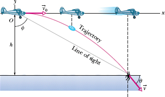
Fig. 4-15 A plane drops a rescue capsule while moving at constant velocity in level flight. While the capsule is falling, its horizontal velocity component remains equal to the velocity of the plane.
Then Eq. 4-27 gives us

(b) As the capsule reaches the water, what is its velocity  in unit-vector notation and in magnitude-angle notation?
Solution: One Key Idea is that the horizontal and vertical components of the capsule’s velocity are independent.
A second Key Idea is that the horizontal component vx does not change from its initial value v0x = v0 cos θ0 because there is no horizontal acceleration. Thus, when the capsule reaches the water,

A third Key Idea is that the vertical velocity component vy changes from its initial value v0y = v0 sin θ0 because there is a vertical acceleration. Using Eq. 4-23 and the capsule’s time of fall t = 10.1 s, we find that when the capsule reaches the water,

Thus, when the capsule reaches the water it has the velocity

Using either Eq. 3-6 as a guide or a vector-capable calculator, we find that the magnitude and the angle of  are
are

Figure 4-16 shows a pirate ship 560 m from a fort defending the harbor entrance of an island. A defense cannon, located at sea level, fires balls at initial speed v0 = 82 m/s.
(a) At what angle θ0 from the horizontal must a ball be fired to hit the ship?
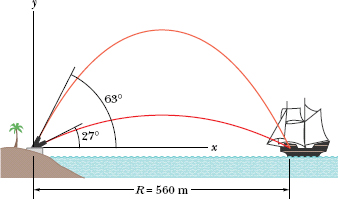
Fig. 4-16 At this range, the pirate ship will be hit at two elevation angles of the cannon.
Solution: The Key Idea here is obvious: A fired cannonball is a projectile, and so the projectile equations apply. We want an equation that relates the launch angle θ0 to the horizontal displacement of the ball as it moves from cannon to ship.
A second Key Idea is that, because the cannon and the ship are at the same height, the horizontal displacement is the range. We can then relate the launch angle θ0 to the range R with Eq. 4-26,

which gives us

The inverse function sin−1 always has two possible solutions. One solution (here, 54.7°) is displayed by a calculator; we subtract it from 180° to get the other solution (here, 125.3°). Thus, Eq. 4-31 gives us

and

The commandant of the fort can elevate the cannon to either of these two angles and (if only there were no intervening air!) hit the pirate ship.
(b) How far should the pirate ship be from the cannon if it is to be beyond the maximum range of the cannonballs?
Solution: We have seen that maximum range corresponds to an elevation angle θ0 of 45°. Thus, from Eq. 4-30 with θ0 = 45°,

As the pirate ship sails away, the two elevation angles at which the ship can be hit draw together, eventually merging at θ0 = 45° when the ship is 690 m away. Beyond that distance the ship is safe.
Figure 4-17a illustrates the ramps for the current world-record motorcycle jump, set by Jason Renie in 2002. The ramps were H = 3.00 m high, angled at θR = 12.0°, and separated by distance D = 77.0 m. Assuming that he landed halfway down the landing ramp and that the slowing effects of the air were negligible, calculate the speed at which he left the launch ramp.
Solution: The Key Idea is that, in flight, Renie and his motorcycle were a projectile. If we consider them to be a single particle, we can use the projectile equations.
Launch. We place the origin of an xy coordinate system on the ground just below the launch point. Then Renie’s coordinates at the instant of launch (at time t = 0) were x0 = 0, y0 = H = 3.00 m. Because he drove straight off the ramp, the launch angle θ0 was equal to the ramp angle θR (Fig. 4-17b): θ0 = θR = 12.0°.
Landing. In Fig. 4-17c, the distance along the ramp is L, which forms the hypotenuse of a right triangle. Renie landed halfway down the ramp and thus at distance L/2 along the ramp. You can show that the landing point was located at half the height H of the ramp and at half the horizontal length d of the ramp. Thus, the landing point had a vertical coordinate

To find the horizontal coordinate x of the landing point, we first find the horizontal length of the ramp:

Then we can find the horizontal coordinate:

Finding launch speed v0. We use Eq. 4-21 to relate v0 to the horizontal displacement x − x0:

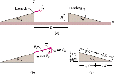
Fig. 4-17 (a) The launch and landing ramps used in a motorcycle jump, with launch velocity  0. (b) The launch velocity
  0 (at launch angle θ0) has an x component v0 cos θ0 and a y component v0 sin θ0. (c) The landing point is halfway down the landing ramp.
We cannot solve this equation for v0 because we do not know Renie’s time of flight t. Because we are stuck on the horizontal axis, let us switch to the vertical axis. Equation 4-22 relates v0 to the vertical displacement y − y0:

Again we are stuck because we cannot find v0 without knowing t. Note, however, that Eqs. 4-32 and 4-33 contain the same two unknowns: v0 (desired) and t (undesired). Thus we can solve Eq. 4-32 for t,

and then substitute the result into Eq. 4-33, to eliminate t:

where we have used the identity tan θ = (sin θ)/(cos θ). Substituting known data, we have

To take off from a ramp at this speed must be terrifying. Actually, Renie had to take off faster than 156 km/h to make the jump because during the flight he and the motorcycle were slowed considerably by the air.
PROBLEM-SOLVING TACTICS
TACTIC 1 : Numbers Versus Algebra
One way to avoid rounding errors and other numerical errors is to solve problems algebraically, substituting numbers only in the final step. That would have been easy to do in Sample Problems 4-6 to 4-8, and that is the way experienced problem solvers operate. In these early chapters, however, we prefer to solve most problems in parts, to give you a firmer numerical grasp of what is going on. Later we shall stick to the algebra longer.
Leave a Reply