A second major type of fuel cell is the SOFC. Here the electrolyte is a ceramic material that conducts oxygen ions. The electrode reactions for a SOFC were provided in Table 9.2. Note that in contrast to the PEMFC, although the overall reaction is the same, water is produced at the anode rather than the cathode. Additionally, the charge carrier is the oxygen ion and not a proton.
Just as in PEMFCs, we desire the electrolyte to be a fast ion conductor, an electronic insulator, and a barrier to prevent mixing of the fuel and oxidant gases. There are three general classes of electrolytes used in SOFCs as shown in Table 9.4. We will discuss only the most common one, zirconia, in any detail.
Table 9.4 Types of Electrolytes Used in SOFCs
| ZrO2, zirconia based | YSZ (yttria-stabilized zirconia), fluorite structure, most common electrolyte | 700–1000 °C |
| CeO2, ceria based | Lower temperature, fluorite structure | 600 °C |
| LaGaO3 | Perovskite structure | 800 °C |
Zirconia is a ceramic with low intrinsic conductivity. The crystal structure of zirconia changes with temperature: monoclinic at room temperature, tetragonal, and finally cubic at high temperatures. It is the cubic structure that is of interest because of its ionic conductivity. The cubic fluorite structure is face centered cubic (fcc) with O2− filling the tetrahedral interstitial sites. Zirconia is typically doped with yttria. Since Y has three valence electrons compared to four for Zr, O2−vacancies are created to preserve charge neutrality as shown in Figure 9.14. This doping behavior is analogous to doping of semiconductors (Chapter 15). The replacement of two Zr4+ with two Y3+ creates an oxygen vacancy. The vacancies created by these substitutional cations with a different charge provide a means for more facile charge transport in the ceramic. Yttria also serves a second function. The crystal structure of zirconia changes with temperature, as noted previously, through displacive transformations; that is, no bonds are broken when changing from cubic to monoclinic structures. However, large volume changes accompany these phase changes and cause zirconia to crack during cooling. The addition of a small amount of yttria stabilizes the tetragonal and cubic structures so that a metastable cubic structure is preserved even at low temperatures. Hence, these materials are called yttria-stabilized zirconia (YSZ).
The existence of these vacancies provides a conduction mechanism for the ceramic. The ability of the oxygen ions to move depends on whether an adjacent site is empty. Oxygen hops through these vacancy sites by a process called vacancy diffusion as shown in Figure 9.15. The addition of Y creates more vacancies, and oxygen now has room to move more easily, much faster than by interchange or interstitial mechanisms. This phenomenon is typically expressed in terms of ionic conductivity, κ. Recall our definition for conductivity (Equation 4.7):
ui is the mobility of the ion, zi its charge, and ci is the concentration of the species. The ability of oxygen to move depends on the number of vacancies (concentration) and the energy barrier or activation energy for exchange. The vacancy concentration increases with increased levels of doping (Y addition), and this simple model predicts that the conductivity increases linearly with doping. The actual behavior is more complex, and the percent doping used in YSZ is about 8%, near the point of maximum conductivity. The ionic conductivity is strongly dependent on temperature, which is shown in Figure 9.16. This dependence is again explained in terms of the mobility of the oxygen. There is an energy barrier to the exchange of atoms with the vacancies, and with increasing temperature the mobility follows an Arrhenius relationship. Temperatures in the range of 700–1000 °C are needed for a practical YSZ-based fuel cell.

O2− is the only ion that is mobile, but YSZ has a very small electronic conductivity (σ) that depends on the partial pressure of oxygen. When speaking of the transference number for SOFCs, it is generally defined as
(9.21)![]()
Here this quantity has a meaning similar to that used previously, namely, the fraction of current carried by the oxygen ion in the absence of concentration gradients. In contrast to liquid electrolytes, the concern is that the minor electronic conductivity is effectively a small short in the cell. In contrast to YSZ, ceria has an appreciable electronic conductivity.
As with any electrochemical system, the voltage of a solid oxide cell can be expressed as
(4.58a)![]()
The first polarization is the ohmic loss, and it is proportional to current density. This includes the resistance of the electrolyte, electrodes, and any interfacial or contact resistances. Activation and concentration polarizations exist at each electrode. We introduced the idea of a charge-transfer resistance in Chapter 4.
(4.62)![]()
For Butler–Volmer kinetics (Chapter 3), this charge-transfer resistance decreases as the current density increases; however, for many SOFCs, the kinetic resistance is nearly constant with current. Therefore, we can adequately express the cell potential for a SOFC with
(9.22)![]()
The concentration polarizations arise due to changes in reactant composition at the electrodes. In this SOFC, we only need concern ourselves with variations in concentration of the gaseous reactants.
A good understanding of the materials of construction, including their microstructure, and the design of a solid oxide cell provide a basis for understanding SOFC polarization curves. Before exploring this, three typical configurations of cells are introduced: anode supported, electrolyte supported, and cathode supported, as shown in Figure 9.17. In short, one of the components is made thicker so that it can provide structural integrity to the cell. The electrolyte is dense, but the other components are porous as shown in Figure 9.18.
The high operating temperature, required for sufficient ionic conductivity, has some advantages. The reaction kinetics at high temperature are typically facile; thus, precious metal catalysts are not essential. What we have referred to as the electrodes are commonly called cathode and anode interlayers within the SOFC community. The anode materials must be catalytically active, chemically compatible, porous for gas access, and have both electronic and ionic conductivity. The coefficient of thermal expansion (CTE) must also be close to that of other components (discussed in more detail in Chapter 10). For SOFCs based on YSZ, the negative electrode is typically formed as cermet, a ceramic and metal mixture of YSZ and Ni. Even though no liquid electrolyte is present, a three-phase boundary is needed just as in other fuel cells. Here the presence of some electronic conductivity in the YSZ electrolyte spreads the reaction zone, allowing for better utilization of the nickel catalyst.
The material requirements of the cathode are similar to those of the anode. Common materials are LaMnO3-based perovskites, which are doped with Sr to improve the electrical conductivity; these materials are known as LSM.
Because of mass transfer, the partial pressure of hydrogen, for example, will be different at the electrode surface, ![]() , and in the bulk gas stream,
, and in the bulk gas stream, ![]() . The concentration polarization is approximated by equilibrium relations,
. The concentration polarization is approximated by equilibrium relations,
(9.23)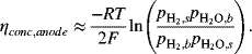

ILLUSTRATION 9.6
The data shown in Figure 9.3 are for an anode-supported solid oxide cell. The cell is operating at atmospheric pressure. The composition of the anode gas is 90% hydrogen and the balance water. At a current density of 10 kA m−2, sketch the partial pressure of hydrogen and oxygen in the support and interlayers. Estimate the polarization at the anode given that the thickness of the support layer is 2 mm with a porosity of 0.45 and tortuosity of 3.4. The gas-phase diffusivity of hydrogen in water at 800 °C is 7.76 × 10⁻⁴ m2 s−1.

From the information in the problem, ![]() and
and ![]() . Fick’s law is used to calculate the partial pressure in the anode interlayer. We neglect the thickness of the interlayer. The flux of hydrogen is also related to the current density with Faraday’s law:
. Fick’s law is used to calculate the partial pressure in the anode interlayer. We neglect the thickness of the interlayer. The flux of hydrogen is also related to the current density with Faraday’s law:
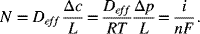
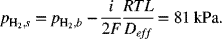
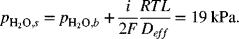
The effective diffusion coefficient is ![]() :
:
Interconnects
The primary function of interconnects is to electrically join the anode of one cell with the cathode of another. This term is a bit broader than what is called a bipolar or separator plate for PEMFCs, but the function is identical. The interconnect term is likely more common in SOFC because of the importance of the tubular design, which is not bipolar (see Problem 9.9).
Refractory metals, such as W, Nb, and Ta, are prohibitively expensive; thus only ceramics are practical at typical operating temperatures of 800–1000 °C. Most often perovskite-type oxide ceramics are used for the interconnects; and these are based on rare-earth chromites. If good oxygen conductors can be found that operate at lower temperatures, say 600 °C, then more common metals and alloys, such as steel, can be used.
The high quality of the waste heat from a SOFC integrates well with a fuel processor, where the reformation reaction is endothermic. There is a good temperature match between the reformer and the waste heat. These high temperatures make the SOFC tolerant of CO in fuel. In fact, only partial reformation is required. Finally, the high-quality waste heat can be used to drive a Rankine bottoming cycle for instance.
The high temperature of SOFCs brings challenges too. The system takes a relatively long time to start up, and SOFCs are generally not well suited to applications that require frequent starting and stopping. There are a relatively small number of materials that can be used at these high temperatures. Sealing is also a major issue and is critical in order to keep the fuel and oxidant gases from mixing. Different materials used in the SOFC expand at different rates with temperature. This expansion is reflected in the coefficient of thermal expansion (CTE) of the material. The CTEs must be matched to prevent large stresses from developing and causing damage to the components.
The effect of temperature on the polarization curve of a SOFC is shown in Figure 9.18. Note that the open-circuit potential doesn’t change much when the temperature is raised from 600 to 800 °C. The largest effect is on the resistance of the electrolyte, which decreases sharply as the temperature is increased.
Closure
In this chapter, the basic operation of a fuel cell has been examined. We learned that fuel cells are classified by their electrolytes, and this is a good starting point to understanding the behavior of any fuel-cell system. Two electrolytes were discussed in detail: proton-exchange membranes and solid oxide conducting ceramics. The most important feature of a fuel cell is its current–voltage relationship, or polarization curve. These curves can be understood in terms of fundamental electrochemical concepts: equilibrium potential, kinetic polarization, ohmic losses, and mass-transfer limitations.
Further Reading
- Huang, K. and Goodenough, J.B. (2009) Solid Oxide Fuel Cell Technology: Principles, Performance and Operations, Woodhead Publishing.
- Larminie, J. and Dicks, A. (2003) Fuel Cell Systems Explained, SAE International.
- Mench, M. (2008) Fuel Cell Engines, John Wiley & Sons, Inc., New York.
- Minh, N.Q. and Takahashi, T. (1995) Science and Technology of Ceramic Fuel Cells, Elsevier Science.
- O’Hayre, R.P. Cha, S.-W., Colella, W.G., and Prinz, F.B. (2009) Fuel Cell Fundamentals, John Wiley & Sons, Inc., New York.
- Singhal, S.C. and Kendall, K. (2003) High-Temperature Solid Oxide Fuel Cells: Fundamentals, Design and Applications, Elsevier Science.
- Srinivasan, S. (2006) Fuel Cells: From Fundamentals to Applications, Springer.
Problems
9.1. Calculate the voltage efficiency, ![]() , for a fuel cell operating at 0.65 V at standard conditions. The product water is a liquid, the oxidant is air, and the following fuels are used:
, for a fuel cell operating at 0.65 V at standard conditions. The product water is a liquid, the oxidant is air, and the following fuels are used:
- Methane, CH4
- Liquid methanol, CH3OH
- Hydrogen, H2
- Liquid formic acid, HCOOH
9.2. In the development of low-temperature fuel cells, many electrolytes were explored. For a liquid acid type of electrolyte, the phosphoric acid fuel cell was commercialized. However, because of the adsorption of phosphate ions that blocks the access of oxygen, the reduction of oxygen is actually faster in sulfuric acid than it is in phosphoric acid. Given this, discuss possible reasons why phosphoric acid was selected over sulfuric acid for development. Hint: Think about the properties of the electrolyte that are important for fuel-cell applications.
9.3. The electrolyte for a molten carbonate fuel cell is a liquid salt mixture of lithium and potassium carbonate (Li2CO3 and K2CO3). Suggest the electrode reactions for molten carbonate chemistry. The reactants are hydrogen and oxygen, as is common for fuel cells. In addition, carbon dioxide is consumed at the cathode and produced at the anode. How might these high-temperature cells be designed so that the anode and cathode do not short out and so that an effective triple phase boundary is achieved? Discuss the importance of managing gaseous CO2 in these cells.
9.4. The performance curves in the figure can be fit with a theoretical curve (J. Electrochem. Soc., 152, A1290 (1985)). The fitting parameters are shown below. Focus on just two parameters, jD and Rint. What do these parameters represent, and how do their values impact the shape of the performance curves? Discuss the physical changes that were likely made to the cell to achieve the observed changes in performance.
| Curve | U [V] | b [V] | j [A·m−2] | jD [A·m−2] | −ln (k) | Rint [μΩ·m2] |
| 1 | 1.05 | 0.026 | 2772 | 9273 | 10.18 | 11.0 |
| 2 | 1.05 | 0.026 | 1014 | 14066 | 10.72 | 10.2 |
| 3 | 1.05 | 0.026 | 1014 | 17023 | 11.01 | 8.0 |
| 4 | 1.05 | 0.026 | 1014 | 28381 | 7.0 | 6.8 |
9.5. Shown are polarization data for a PEM fuel cell operating on hydrogen air at 70 °C and atmospheric pressure. Also shown is the Tafel plot, where ohmic and anodic polarizations have been removed. By means of a sketch, show how these plots would change under the following conditions:
- The pressure is raised to 300 kPa.
- The oxidant is changed to pure oxygen in place of air.
- The platinum loading of the cathode catalyst (mg Pt cm−2) is doubled.
9.6. A polarization curve for a molten carbonate fuel cell is shown in the figure. The temperature is 650 °C, and the electrolyte is a eutectic mixture of lithium and potassium carbonate. Discuss the polarization curve in terms of the four principal factors that influence the shape and magnitude of the curve.
9.7. A series of polarization curves at different temperatures for a direct methanol fuel cell are shown in the figure. This cell uses a Nafion separator. It is suggested that Nafion is permeable to methanol. Could this explain why the open-circuit potential is so low? What information about the cell can be inferred from these data specifically?
9.8. A series of anode-supported SOFCs were tested at 800 °C. The only parameter that was changed was the thickness of the electrolyte. Data for the cell resistance measured with current interruption are shown in the table. Determine the conductivity of the YSZ electrolyte and the fraction of the resistance that can be ascribed to the interlayers, current collectors, and contact resistances combined.
| Thickness [μm] | Resistance [Ω·cm2] |
| 4 | 0.100 |
| 8 | 0.105 |
| 14 | 0.120 |
| 20 | 0.140 |
9.9. The tubular configuration is the most developed design for the solid oxide fuel cell. This design is shown in the figure. Air flows through the center and fuel flows over the outside. The separator is YSZ (yttria-stabilized zirconia), an oxygen ion (O2−) conductor. What is the direction of current flow in the cell? How is the current carried in the cell? Sketch the potential and current distributions in the cell. Use the approximate schematic shown in the figure, where one half of the tube has been flattened out. Why is the performance (current–potential relationship) of the tubular design much lower than that of planar designs?
9.10. A proton-exchange membrane (PEM) fuel cell is fabricated with a separator that is 100 μm thick and has a conductivity of 5 S·m−1. The cell is operating on hydrogen and air.
- If the open-circuit potential is 0.96 V, which corresponds to 20 A·m−2 of crossover current, calculate the maximum power per unit area if only ohmic losses in the separator are considered.
- For the ohmically limited cell in part (a), sketch the current–voltage relationship. On the same graph compare the performance of a cell that includes kinetic- and mass-transfer polarization. Explain the curve.
9.11. After a prolonged shutdown of a PEM FC, both the anode and the cathode will contain air. During start-up, a front of hydrogen displaces the air in the fuel channels. This condition is illustrated in the figure and was first reported by Reiser et al., Electrochem. Solid State Lett., 8, A273 (2005). This situation is clearly transient and 2D in nature. Nonetheless, we can gain insight by examining a one-dimensional, steady-state analog, shown in the figure.
The two cells are electrically connected in parallel to an external load. Cell (1) has air and fuel provided normally, and the second cell (2) has air on both electrodes. At the positive electrode of the cell (2) oxygen evolution or carbon corrosion can occur. At the negative electrode of cell (2) we can expect oxygen reduction. For any reasonable potential, the current through the second cell will be small and we may assume that the solution potential, ![]() , is nearly constant between the anode and cathode of that cell. The anodic and cathodic currents for cell (2) must be equal to each other. Assuming Tafel kinetics for oxygen reduction and carbon corrosion, and assuming the kinetics for hydrogen oxidation to be fast, estimate the overpotential for carbon corrosion in cell (2) as a function of the measured potential of the cell Vc.
, is nearly constant between the anode and cathode of that cell. The anodic and cathodic currents for cell (2) must be equal to each other. Assuming Tafel kinetics for oxygen reduction and carbon corrosion, and assuming the kinetics for hydrogen oxidation to be fast, estimate the overpotential for carbon corrosion in cell (2) as a function of the measured potential of the cell Vc.
9.12. For the situation described in Problem 11, sketch current and potential in the separator of the fuel cell during start–stop phenomena, that is, during the situation illustrated in the figure with Problem 9.11.
9.13. How does the maximum power density improve if the separator is decreased in thickness from 50 to 25 μm. Assume that there are no mass-transfer limitations.
9.14. Redo the maximum power calculation for Illustration 9.5 assuming that there is a mass-transfer limitation of 15,000 A·m−2 for the cathode.
9.15. You are evaluating a new technology for a hydrogen-air fuel cell. The incumbent is the traditional proton-exchange membrane fuel cell (PEMFC). For both fuel cells, the overall reaction is

At the anode of the PEMFC, hydrogen is oxidized; and at the cathode, oxygen is reduced. It is well known that for PEMFCs the oxygen electrode is the major limitation. Although the anode reaction is unchanged, the new approach breaks the oxygen reduction reaction into two easier parts. A mediator is an electroactive species that acts as an electron shuttle. At the positive electrode, the mediator (M) reacts as follows:

In a separate nonelectrochemical reaction, the mediator is regenerated outside the cell.

On the right are two polarization curves, one for the PEMFC and one for the new concept. Both curves are taken at 80 °C.
Compare and contrast the polarization curves of the two types of fuel cells. Specifically address the open-circuit potential as well as kinetic, ohmic, and mass-transfer losses.
9.16. In Illustration 9.5, it was assumed that the hydrogen crossover current was 10 A·m−2. Estimate the permeability (Equation 4.72) for hydrogen through the membrane. Assume c is 30,000 mol·m−3. There is also permeation of oxygen across the membrane. The oxygen permeation is smaller than hydrogen, but not insignificant. Justify why this crossover is ignored in calculating the open-circuit potential in Illustration 9.5.
9.17. You are investigating mass-transfer limitations in a new cathode structure that your research group has developed for a PEM fuel cell. Consider an electrode with possible limitations to mass transfer in either the gas or liquid phase as illustrated in the cartoon.
- Using the figure as a guide, develop a relationship for an overall mass-transfer coefficient, in terms of a pressure driving force; in other words, determine the expression for K in the equation:
 where the concentration at L is expressed in terms of pi*, the hypothetical partial pressure in equilibrium with the solution at composition xi; that is,
  . The final answer should include the following parameters:
- kc: mass-transfer coefficient for gas phase, m·s−1
- L: the thickness of the liquid film, m
- cT: the total concentration in the liquid, mol m−3
- D: diffusion coefficient of oxygen in the liquid, m2·s−1
- H: Henry’s law coefficient, Pa
- Data have been collected for the limiting current on air (21% oxygen with balance nitrogen) and Helox (21% oxygen with the balance helium). The limiting currents and the binary gas-phase diffusivity coefficients are given below. These were collected at ambient pressure and 80 °C.Limiting current [A·m−2]Diffusivity of oxygenAir15,0002.47 × 10−5 m2·s−1Helox19,5008.97 × 10−5 m2·s−1Assume that the Sherwood number is a constant, 3.66. The following additional data are provided:DO2, diffusion coefficient for liquid phaseHO2/cT·, Henry’s law constant3.0 × 10−9 m2·s−18.0 × 10⁴ Pa·m3·mol−1
Estimate the fraction of mass-transfer resistance that can be ascribed to gas phase. What does this suggest about the thickness of the liquid film?
9.18. How would flooding affect the polarization curve of a PEM fuel cell. What about dryout? Sketch the polarization curves for normal, dryout, slight flooding, and severe flooding operation.
9.19. Sketch composition of water across membrane in a PEM fuel cell for the following conditions:
- Both streams humidified, no current flow
- One humidified, one dry, no current
- One humidified, one dry, low and high current (from humidified to dry)
9.20. Data for the polarization of a solid oxide fuel cell/electrolyzer are provided below. (J. Electrochem. Soc., 158, B514–B525 (2011)). These potentials are reported with respect to a hydrogen reference electrode. The temperature of operation is 973 K. The ohmic resistance of the cell is 0.067 Ω·cm2. After removing ohmic polarization, how well can the data be represented by Butler–Volmer kinetic expression? Discuss whether the BV expression is appropriate for these data.
| i [A·m−2] | Vcell [V] | i [A·m−2] | Vcell [V] |
| −6981 | 1.5006 | 930 | 0.9047 |
| −4871 | 1.3554 | 2799 | 0.7545 |
| −4871 | 1.3554 | 4753 | 0.6020 |
| −2946 | 1.2074 | 6836 | 0.4518 |
| −967 | 1.0549 | 9328 | 0.3000 |
9.21. If the loading of the cathode of a PEM fuel cell is doubled, what would you expect to happen to polarization curve? What if the pressure is doubled?
9.22. Derive Equation 9.24 for the concentration overpotential of the anode of a solid oxide fuel cell assuming that only the thermodynamic contribution is important (see Chapter 4).
9.23. Estimate the limiting current for the cathode of a SOFC at 900 °C and ambient pressure. Assume that air is supplied to the cathode: yO2 = 0.21. The cathode current collector is 0.7 mm thick and has a porosity of 0.5 and a tortuosity of 6.
9.24. From the data provided, calculate the transference number of oxygen for doped ceria and YSZ. How would open-circuit potentials of the two cells compare?
| YSZ | κ = 7 S·m−1 | σ = 0.1 S·m−1 |
| Doped ceria | κ = 15 S·m−1 | σ = 10 S·m−1 |
9.25. Calculate the maximum power for three designs of SOFC: anode supported, cathode supported, and electrolyte supported. Assume operation at 800 oC and 1 bar. The cathode operates on air and the composition of the anode gas is 90% hydrogen, with the balance water. The diffusivity of oxygen in air at this temperature is 1.9 × 10⁻⁴ m2·s−1, and that of hydrogen in water is 7.8 × 10⁻⁴ m2·s−1. The anode is 45% porous and has a tortuosity of 2.5. The porosity of the cathode is 40% and the tortuosity is 3. Transport in the anode approximates equimolar counter-diffusion. In contrast, transport in the cathode is best described by diffusion of oxygen through stagnant nitrogen. In determining the cell voltage, you should include ohmic, surface, and concentration overpotentials. The conductivity of the solid electrolyte at 800 oC is 10 S·m−1. Anode kinetics are approximately linear with an exchange current density of 5300 A·m−2. The surface overpotential at the cathode, which is negative, can be approximated as
| Electrolyte supported (μm) | Anode supported (μm) | Cathode supported (μm) | |
| Anode thickness | 50 | 750 | 50 |
| Cathode thickness | 50 | 50 | 750 |
| Electrolyte thickness | 500 | 40 | 40 |
9.26.
A molten carbonate fuel cell uses hydrogen as the fuel and air as oxidant and operates at 650 °C, ambient pressure. The electrolyte layer is 0.5 mm thick and has a conductivity of 100 S·m−1.
- If the partial pressure of carbon dioxide on the anode and cathode side were 20 and 10 kPa, respectively, predict the theoretical voltage of the cell.
- Estimate the highest possible operating cell voltage for this cell at 2000 A·m−2.
- Estimate the reduction in electrolyte layer thickness needed to triple the power density of the cell at the same cell potential. (This problem was suggested by S.R. Narayan).
CopycopyHighlighthighlightAdd NotenoteGet Linklink
Leave a Reply