An irreversible, adiabatic pump or compressor generates entropy. If these devices are reversible, they are isentropic. Examples of both are shown in Fig. 4.12. The calculations are generally straightforward. Consider the case where the inlet state and the outlet pressure is known. First, the reversible outlet state is determined based on the isentropic condition, and the enthalpy at the reversible state is known. The most common estimate for compressors is described in Example 2.12 on page 76. Even though it is intended for ideal gases, it is convenient for many applications and often provides a reasonable first approximation. The most common estimate for pumps is described in Eqn. 2.32 on page 55. These both pertain to reversible processes. The efficiency can then be used to determine the actual outlet enthalpy and work, using Eqn. 4.46.

Figure 4.12. Illustrations of pathways for reversible and irreversible pumps and compressors. The P-H diagram is for a system like Fig. 4.7(a).
Example 4.16. Isothermal reversible compression of steam
In Example 2.12 on page 76, we mentioned that computing the work for isothermal compression of steam was different from computing the work for an ideal gas. Now that you know about the entropy balance, use it to compute the work of continuously, isothermally, and reversibly compressing steam from 5 bars and 224°C to 25 bars. Compare to the result of the ideal gas formula.
Solution
Energy balance: ΔH = Q + W. Entropy balance: ΔS = Q/T. Note that ΔS ≠ 0, even though this is a reversible process. Sgen = 0, but the process is not adiabatic. From the steam tables, we note that 224°C and 25 bars is practically equal to the saturated vapor. For the vapor at 224°C and 25 bars, interpolation gives H = 2910.5, S = 7.1709. Noting Q = TΔS, Q = (224 + 273.15)(6.2558 – 7.1709) = –454.94; W = (2801.9 – 2910.5) + 454.94 = 346.3 J/g.
By the ideal gas formula, W = 8.314(4.04)(224 + 273.15)ln(5)/18 = 1493.1 J/g.
The work is less for the real vapor because of the intermolecular attractions. The difference was particularly large in this case because the final pressure was fairly high (> 10 bars).
Multistage Compression
During adiabatic compression of vapors, the temperature rises. This can cause equipment problems if the temperature rise or pressure ratio (Pout/Pin) is too large. To address this problem, interstage cooling is used to lower the gas temperature between compression stages. Such operations are common when high pressures need to be reached. A schematic of a compressor with interstage cooling is shown in Fig. 4.13. The total work for multistage compression is generally given by summing the work of each stage using Eqn. 2.69 on page 77. However, the ideal gas law becomes less reliable as the stagewise inlet pressure increases. If the inlet pressure is above 10 bars and the reduced temperature is less than 1.5, nonideality effects should be evaluated. Methods to evaluate gas non-idealities and to calculate entropy for all manner of non-ideal gases are discussed in Unit II. For common refrigerants, it is convenient to apply charts that are functionally equivalent to the steam tables. The charts are difficult to read and precision is relatively low compared to using the steam tables. Example 4.17 illustrates the procedure using the refrigerant R134a.

Figure 4.13. Illustration of a multistage compression and the corresponding P-H diagram. On the P-H diagram, the compressors appear as the curves of increasing pressure and the heat exchangers are the horizontal lines at constant pressure.
Example 4.17. Compression of R134a using P-H chart
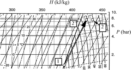
A compressor operates on R134a. The inlet to the compressor is saturated vapor at –20°C. The outlet of the compressor is at 7.7 bar and ηC = 0.8. Find the reversible and required work (kJ/kg) and the outlet temperature of the compressor.
Solution
An inset of the P-H diagram from Appendix E is shown below. The axis labels and superheated temperature labels have been translated on the inset diagram.

The inlet state is located at the intersection of the –20°C isotherm and the saturated vapor line. The enthalpy is found by following the vertical lines to the axis and H = 386.5 kJ/kg. (Note: This accurate value was found from the accompanying saturation table, but the schematic value is consistent, though less accurate.) The reversible outlet state is found by following an isentropic state up to 7.7 bars. One set of the diagonal lines are isentropes, and we visually interpolate to keep the same relative position between the isentropes at 7.7 bar at the state labeled 2′. By following the vertical lines to the axis, H2′ = 424 kJ/kg. The reversible work is WS′ = 424 – 386.5 = 37.5 kJ/kg. The actual work is WS = WS′ / 0.8 = 47 kJ/kg. The actual outlet state is shifted to the right at 7.7 bar at an enthalpy value of H2 = 386.5 + 47 = 433.5 kJ/kg. The reversible outlet is just near 38°C. The actual outlet is near 48°C.
Leave a Reply