As we discussed in Chapter 7, when a force F causes a rigid body of mass m to accelerate along a coordinate axis, the force does work W on the body. Thus, the body’s kinetic energy ![]() can change. Suppose it is the only energy of the body that changes. Then we relate the change ΔK in kinetic energy to the work W with the work–kinetic energy theorem (Eq. 7-10), writing
can change. Suppose it is the only energy of the body that changes. Then we relate the change ΔK in kinetic energy to the work W with the work–kinetic energy theorem (Eq. 7-10), writing

For motion confined to an x axis, we can calculate the work with Eq. 7-32,

This reduces to W = Fd when F is constant and the body’s displacement is d. The rate at which the work is done is the power, which we can find with Eqs. 7-43 and 7-48,

Now let us consider a rotational situation that is similar. When a torque accelerates a rigid body in rotation about a fixed axis, the torque does work W on the body. Therefore, the body’s rotational kinetic energy ![]() can change. Suppose that it is the only energy of the body that changes. Then we can still relate the change ΔK in kinetic energy to the work W with the work–kinetic energy theorem, except now the kinetic energy is a rotational kinetic energy:
can change. Suppose that it is the only energy of the body that changes. Then we can still relate the change ΔK in kinetic energy to the work W with the work–kinetic energy theorem, except now the kinetic energy is a rotational kinetic energy:


Here, I is the rotational inertia of the body about the fixed axis and ωi and ωf are the angular speeds of the body before and after the work is done, respectively.
Also, we can calculate the work with a rotational equivalent of Eq. 10-50,

where ![]() is the torque doing the work W, and θi and θf are the body’s angular positions before and after the work is done, respectively. When
is the torque doing the work W, and θi and θf are the body’s angular positions before and after the work is done, respectively. When ![]() is constant, Eq. 10-53 reduces to
is constant, Eq. 10-53 reduces to

The rate at which the work is done is the power, which we can find with the rotational equivalent of Eq. 10-51,

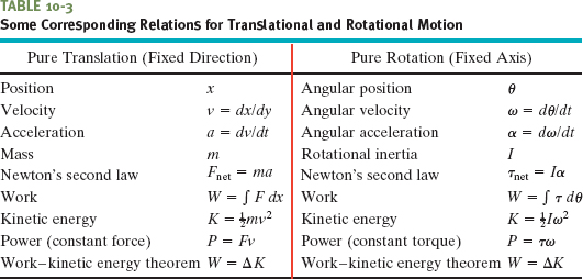
Table 10-3 summarizes the equations that apply to the rotation of a rigid body about a fixed axis and the corresponding equations for translational motion.
Proof of Eqs. 10-52 through 10-55
Let us again consider the situation of Fig. 10-17, in which force ![]() rotates a rigid body consisting of a single particle of mass m fastened to the end of a massless rod. During the rotation, force
rotates a rigid body consisting of a single particle of mass m fastened to the end of a massless rod. During the rotation, force ![]() does work on the body. Let us assume that the only energy of the body that is changed by
does work on the body. Let us assume that the only energy of the body that is changed by ![]() is the kinetic energy. Then we can apply the work–kinetic energy theorem of Eq. 10-49:
is the kinetic energy. Then we can apply the work–kinetic energy theorem of Eq. 10-49:

Using ![]() and Eq. 10-18 (v = ωr), we can rewrite Eq. 10-56 as
and Eq. 10-18 (v = ωr), we can rewrite Eq. 10-56 as

From Eq. 10-33, the rotational inertia for this one-particle body is I = mr2. Substituting this into Eq. 10-57 yields

which is Eq. 10-52. We derived it for a rigid body with one particle, but it holds for any rigid body rotated about a fixed axis.
We next relate the work W done on the body in Fig. 10-17 to the torque ![]() on the body due to force
on the body due to force ![]() . When the particle moves a distance ds along its circular path, only the tangential component Ft of the force accelerates the particle along the path. Therefore, only Ft does work on the particle. We write that work dW as Ft ds. However, we can replace ds with r dθ, where dθ is the angle through which the particle moves. Thus we have
. When the particle moves a distance ds along its circular path, only the tangential component Ft of the force accelerates the particle along the path. Therefore, only Ft does work on the particle. We write that work dW as Ft ds. However, we can replace ds with r dθ, where dθ is the angle through which the particle moves. Thus we have

From Eq. 10-40, we see that the product Ftr is equal to the torque ![]() , so we can rewrite Eq. 10-58 as
, so we can rewrite Eq. 10-58 as

The work done during a finite angular displacement from θi to θf is then

which is Eq. 10-53. It holds for any rigid body rotating about a fixed axis. Equation 10-54 comes directly from Eq. 10-53.
We can find the power P for rotational motion from Eq. 10-59:

which is Eq. 10-55.
Let the disk in Sample Problem 10-8 and Fig. 10-18 start from rest at time t = 0. What is its rotational kinetic energy K at t = 2.5 s?
Solution: We can find K with Eq. 10-34 ![]() . We already know that
. We already know that ![]() , but we do not yet know ω at t = 2.5 s. A Key Idea, though, is that the angular acceleration α has the constant value of −24 rad/s2, so we can apply the equations for constant angular acceleration in Table 10-1. Because we want ω and know α and ω0 (= 0), we use Eq. 10-12
, but we do not yet know ω at t = 2.5 s. A Key Idea, though, is that the angular acceleration α has the constant value of −24 rad/s2, so we can apply the equations for constant angular acceleration in Table 10-1. Because we want ω and know α and ω0 (= 0), we use Eq. 10-12

Substituting ω = αt and ![]() into Eq. 10-34, we find
into Eq. 10-34, we find

We can also get this answer with a different Key Idea: We can find the disk’s kinetic energy from the work done on the disk. First, we relate the change in the kinetic energy of the disk to the net work W done on the disk, using the work– kinetic energy theorem of Eq. 10-52 (Kf − Ki = W). With K substituted for Kf and 0 for Ki, we get

Next we want to find the work W. We can relate W to the torques acting on the disk with Eq. 10-53 or 10-54. The only torque causing angular acceleration and doing work is the torque due to force ![]() on the disk from the cord. From Sample Problem 10-8, this torque is equal to −TR. Another Key Idea is that because α is constant, this torque also must be constant. Thus, we can use Eq. 10-54 to write
on the disk from the cord. From Sample Problem 10-8, this torque is equal to −TR. Another Key Idea is that because α is constant, this torque also must be constant. Thus, we can use Eq. 10-54 to write

We need one more Key Idea: Because α is constant, we can use Eq. 10-13 to find θf − θi. With ωi = 0, we have

Now we substitute this into Eq. 10-61 and then substitute the result into Eq. 10-60. With T = 6.0 N and α = −24 rad/s2 (from Sample Problem 10-8), we have

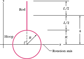
A rigid sculpture consists of a thin hoop (of mass m and radius R = 0.15 m) and a thin radial rod (of mass m and length L = 2.0R), arranged as shown in Fig. 10-20. The sculpture can pivot around a horizontal axis in the plane of the hoop, passing through its center.
(a) In terms of m and R, what is the sculpture’s rotational inertia I about the rotation axis?
Solution: A Key Idea here is that we can separately find the rotational inertias of the hoop and the rod and then add the results to get the sculpture’s total rotational inertia I. From Table 10-2h, the hoop has rotational inertia ![]() about its diameter. From Table 10-2e, the rod has rotational inertia Icom = mL2/12 about an axis through its center of mass and parallel to the sculpture’s rotation axis. To find its rotational inertia Irod about that rotation axis, we use Eq. 10-36,
about its diameter. From Table 10-2e, the rod has rotational inertia Icom = mL2/12 about an axis through its center of mass and parallel to the sculpture’s rotation axis. To find its rotational inertia Irod about that rotation axis, we use Eq. 10-36,

Fig. 10-20 A rigid sculpture consisting of a hoop and a rod can rotate around a horizontal axis.
the parallel-axis theorem:

where we have used the fact that L = 2.0R and where the perpendicular distance between the rod’s center of mass and the rotation axis is h = R + L/2. Thus, the rotational inertia I of the sculpture about the rotation axis is

(b) Starting from rest, the sculpture rotates around the rotation axis from the initial upright orientation of Fig. 10-20. What is its angular speed ω about the axis when it is inverted?
Solution: Three Key Ideas are required here:
1. We can relate the sculpture’s speed ω to its rotational kinetic energy K with Eq. 10-34 ![]() .
.
2. We can relate K to the gravitational potential energy U of the sculpture via the conservation of the sculpture’s mechanical energy E during the rotation. Thus, during the rotation, E does not change (ΔE = 0) as energy is transferred from U to K.
3. For the gravitational potential energy we can treat the rigid sculpture as a particle located at the center of mass, with the total mass 2m concentrated there.
We can write the conservation of mechanical energy (ΔE = 0) as

As the sculpture rotates from its initial position at rest to its inverted position, when the angular speed is ω, the change ΔK in its kinetic energy is

From Eq. 8-7 (ΔU = mg Δy), the corresponding change ΔU in the gravitational potential energy is

where 2m is the sculpture’s total mass and Δycom is the vertical displacement of its center of mass during the rotation.
To find Δycom, we first find the initial location ycom of the center of mass in Fig. 10-20. The hoop (with mass m) is centered at y = 0. The rod (with mass m) is centered at y = R + L/2. Thus, from Eq. 9-5, the sculpture’s center of mass is at

When the sculpture is inverted, the center of mass is this same distance R from the rotation axis but below it. Therefore, the vertical displacement of the center of mass from the initial position to the inverted position is Δycom = −2R.
Now let’s pull these results together. Substituting Eqs. 10-63 and 10-64 into 10-62 gives us

Substituting I = 4.83mR2 from (a) and Δycom = −2R from above and solving for ω, we find

Leave a Reply