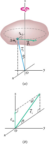
We next evaluate the angular momentum of a system of particles that form a rigid body that rotates about a fixed axis. Figure 11-15a shows such a body. The fixed axis of rotation is a z axis, and the body rotates about it with constant angular speed ω. We wish to find the angular momentum of the body about that axis.

Fig. 11-15 (a) A rigid body rotates about a z axis with angular speed ω. A mass element of mass Δmi within the body moves about the z axis in a circle with radius r⊥i. The mass element has linear momentum ![]() i, and it is located relative to the origin O by position vector
i, and it is located relative to the origin O by position vector ![]() i. Here the mass element is shown when r⊥i is parallel to the x axis. (b) The angular momentum
i. Here the mass element is shown when r⊥i is parallel to the x axis. (b) The angular momentum ![]() i, with respect to O, of the mass element in (a). The z component ℓiz is also shown.
i, with respect to O, of the mass element in (a). The z component ℓiz is also shown.
We can find the angular momentum by summing the z components of the angular momenta of the mass elements in the body. In Fig. 11-15a, a typical mass element, of mass Δmi, moves around the z axis in a circular path. The position of the mass element is located relative to the origin O by position vector ![]() i. The radius of the mass element’s circular path is r⊥i, the perpendicular distance between the element and the z axis.
i. The radius of the mass element’s circular path is r⊥i, the perpendicular distance between the element and the z axis.
The magnitude of the angular momentum ![]() i of this mass element, with respect to O, is given by Eq. 11-19:
i of this mass element, with respect to O, is given by Eq. 11-19:
ℓi = (ri)(pi)(sin 90°) = (ri)(Δmi vi),
where pi and vi are the linear momentum and linear speed of the mass element, and 90° is the angle between ![]() i and
i and ![]() i. The angular momentum vector
i. The angular momentum vector ![]() i for the mass element in Fig. 11-15a is shown in Fig. 11-15b; its direction must be perpendicular to those of
i for the mass element in Fig. 11-15a is shown in Fig. 11-15b; its direction must be perpendicular to those of ![]() i and
i and ![]() i.
i.
We are interested in the component of ![]() i that is parallel to the rotation axis, here the z axis. That z component is
i that is parallel to the rotation axis, here the z axis. That z component is
ℓiz = ℓi sin θ = (ri sin θ)(Δmi vi) = r⊥i Δmi vi.
The z component of the angular momentum for the rotating rigid body as a whole is found by adding up the contributions of all the mass elements that make up the body. Thus, because v = ωr⊥, we may write

We can remove ω from the summation here because it has the same value for all points of the rotating rigid body.
The quantity ![]() in Eq. 11-30 is the rotational inertia I of the body about the fixed axis (see Eq. 10-33). Thus Eq. 11-30 reduces to
in Eq. 11-30 is the rotational inertia I of the body about the fixed axis (see Eq. 10-33). Thus Eq. 11-30 reduces to

We have dropped the subscript z, but you must remember that the angular momentum defined by Eq. 11-31 is the angular momentum about the rotation axis. Also, I in that equation is the rotational inertia about that same axis.
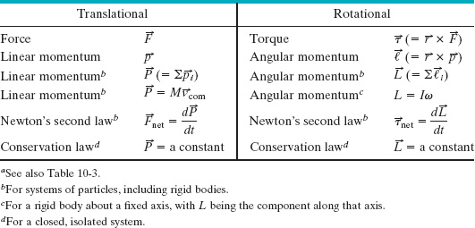
Table 11-1, which supplements Table 10-3, extends our list of corresponding linear and angular relations.
TABLE 11-1 More Corresponding Variables and Relations for Translational and Rotational Motiona

![]() CHECKPOINT 6 In the figure, a disk, a hoop, and a solid sphere are made to spin about fixed central axes (like a top) by means of strings wrapped around them, with the strings producing the same constant tangential force
CHECKPOINT 6 In the figure, a disk, a hoop, and a solid sphere are made to spin about fixed central axes (like a top) by means of strings wrapped around them, with the strings producing the same constant tangential force ![]() on all three objects. The three objects have the same mass and radius, and they are initially stationary. Rank the objects according to (a) their angular momentum about their central axes and (b) their angular speed, greatest first, when the strings have been pulled for a certain time t.
on all three objects. The three objects have the same mass and radius, and they are initially stationary. Rank the objects according to (a) their angular momentum about their central axes and (b) their angular speed, greatest first, when the strings have been pulled for a certain time t.

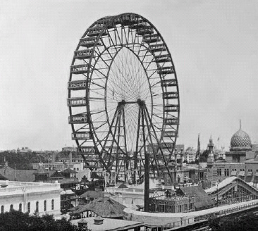
George Washington Gale Ferris, Jr., a civil engineering graduate from Rensselaer Polytechnic Institute, built the original Ferris wheel (Fig. 11-16) for the 1893 World’s Columbian Exposition in Chicago. The wheel, an astounding engineering construction at the time, carried 36 wooden cars, each holding as many as 60 passengers, around a circle of radius R = 38 m. The mass of each car was about 1.1 × 10⁴ kg. The mass of the wheel’s structure was about 6.0 × 10⁵ kg, which was mostly in the circular grid from which the cars were suspended. The wheel made a complete rotation at an angular speed ωF in about 2 min.
(a) Estimate the magnitude L of the angular momentum of the wheel and its passengers while the wheel rotated at ωF.
Solution: The Key Idea here is that we can treat the wheel, cars, and passengers as a rigid object rotating about a fixed axis, at the wheel’s axle. Then Eq. 11-31 (L = Iω) gives the magnitude of the angular momentum of that object. We need to find ωF and the rotational inertia I of this object.
To find I, let us start with the loaded cars. Because we can treat them as particles, at distance R from the axis of rotation, we know from Eq. 10-33 that their rotational inertia is Ipc = MpcR2, where Mpc is their total mass. Let us assume that the 36 cars are each filled with 60 passengers, each of mass 70 kg. Then their total mass is
Mpc = 36[1.1 × 10⁴ kg + 60(70 kg)] = 5.47 × 10⁵ kg
and their rotational inertia is
Ipc = MpcR2 = (5.47 × 10⁵ kg)(38 m)2 = 7.90 × 10⁸ kg · m2.
Next we consider the structure of the wheel. Let us assume that the rotational inertia of the structure is due mainly to the circular grid suspending the cars. Further, let us assume that the grid forms a hoop of radius R, with a mass Mhoop of 3.0 × 10⁵ kg (half the wheel’s mass). From Table 10-2a, the rotational inertia of the hoop is
Ihoop = MhoopR2 = (3.0 × 10⁵ kg)(38 m)2
= 4.33 × 10⁸ kg · m2.
The combined rotational inertia I of the cars, passengers, and hoop is then
I = Ipc + Ihoop = 7.90 × 10⁸ kg · m2 + 4.33 × 10⁸ kg · m2
= 1.22 × 10⁹ kg · m2.
To find the rotational speed ωF, we use Eq. 10-5 (ωavg = Δθ/Δt). Here the wheel goes through an angular displacement of Δθ = 2π rad in a time period Δt = 2 min. Thus, we have


Fig. 11-16 The original Ferris wheel, built in 1893 near the University of Chicago, towered over the surrounding buildings.
Now we can find the magnitude L of the angular momentum with Eq. 11-31:
L = IωF = (1.22 × 10⁹ kg · m2)(0.0524 rad/s)
= 6.39 × 10⁷ kg · m2/s ≈ 6.4 × 10⁷ kg · m2/s. (Answer)
(b) Assume that the fully loaded wheel is rotated from rest to ωF in a time period Δt1 = 5.0 s. What is the magnitude τavg of the average net external torque acting on it during Δt1?
Solution: The Key Idea here is that the average net external torque is related to the change ΔL in the angular momentum of the loaded wheel by Eq. 11-29 ![]() . Because the wheel rotates about a fixed axis to reach angular speed ωF in time period Δt1, we can rewrite Eq. 11-29 as τavg = ΔL/Δt1. The change ΔL is from zero to the answer for part (a). Thus, we have
. Because the wheel rotates about a fixed axis to reach angular speed ωF in time period Δt1, we can rewrite Eq. 11-29 as τavg = ΔL/Δt1. The change ΔL is from zero to the answer for part (a). Thus, we have

Leave a Reply