A torque can cause rotation of a rigid body, as when you use a torque to rotate a door. Here we want to relate the net torque τnet on a rigid body to the angular acceleration α that torque causes about a rotation axis. We do so by analogy with Newton’s second law (Fnet = ma) for the acceleration a of a body of mass m due to a net force Fnet along a coordinate axis. We replace Fnet with τnet, m with I, and a with α, writing

where α must be in radian measure.
Proof of Equation 10-42
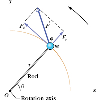
We prove Eq. 10-42 by first considering the simple situation shown in Fig. 10-17. The rigid body there consists of a particle of mass m on one end of a massless rod of length r. The rod can move only by rotating about its other end, around a rotation axis (an axle) that is perpendicular to the plane of the page. Thus, the particle can move only in a circular path that has the rotation axis at its center.
A force ![]() acts on the particle. However, because the particle can move only along the circular path, only the tangential component Ft of the force (the component that is tangent to the circular path) can accelerate the particle along the path. We can relate Ft to the particle’s tangential acceleration at along the path with Newton’s second law, writing
acts on the particle. However, because the particle can move only along the circular path, only the tangential component Ft of the force (the component that is tangent to the circular path) can accelerate the particle along the path. We can relate Ft to the particle’s tangential acceleration at along the path with Newton’s second law, writing

The torque acting on the particle is, from Eq. 10-40,

From Eq. 10-22 (at = αr) we can write this as

The quantity in parentheses on the right is the rotational inertia of the particle about the rotation axis (see Eq. 10-33). Thus, Eq. 10-43 reduces to

For the situation in which more than one force is applied to the particle, we can generalize Eq. 10-44 as

which we set out to prove. We can extend this equation to any rigid body rotating about a fixed axis, because any such body can always be analyzed as an assembly of single particles.
![]() CHECK POINT 7 The figure shows an overhead view of a meter stick that can pivot about the point indicated, which is to the left of the stick’s midpoint. Two horizontal forces,
CHECK POINT 7 The figure shows an overhead view of a meter stick that can pivot about the point indicated, which is to the left of the stick’s midpoint. Two horizontal forces, ![]() and
and ![]() , are applied to the stick. Only
, are applied to the stick. Only ![]() is shown. Force
is shown. Force ![]() is perpendicular to the stick and is applied at the right end. If the stick is not to turn, (a) what should be the direction of
is perpendicular to the stick and is applied at the right end. If the stick is not to turn, (a) what should be the direction of ![]() , and (b) should F2 be greater than, less than, or equal to F1?
, and (b) should F2 be greater than, less than, or equal to F1?


Fig. 10-17 A simple rigid body, free to rotate about an axis through O, consists of a particle of mass m fastened to the end of a rod of length r and negligible mass. An applied force ![]() causes the body to rotate.
causes the body to rotate.
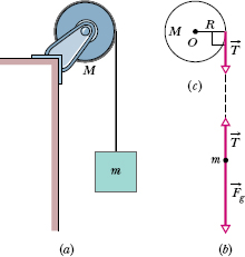
Figure 10-18a shows a uniform disk, with mass M = 2.5 kg and radius R = 20 cm, mounted on a fixed horizontal axle. A block with mass m = 1.2 kg hangs from a massless cord that is wrapped around the rim of the disk. Find the acceleration of the falling block, the angular acceleration of the disk, and the tension in the cord. The cord does not slip, and there is no friction at the axle.
Solution: One Key Idea here is that, taking the block as a system, we can relate its acceleration a to the forces acting on it with Newton’s second law ![]() . Those forces are shown in the block’s free-body diagram in Fig. 10-18b: The force from the cord is
. Those forces are shown in the block’s free-body diagram in Fig. 10-18b: The force from the cord is ![]() , and the gravitational force is
, and the gravitational force is ![]() , of magnitude mg. We can now write Newton’s second law for components along a vertical y axis (Fnet,y = may) as
, of magnitude mg. We can now write Newton’s second law for components along a vertical y axis (Fnet,y = may) as

However, we cannot solve this equation for a because it also contains the unknown T.
Previously, when we got stuck on the y axis, we would switch to the x axis. Here, we switch to the rotation of the disk and use this Key Idea: Taking the disk as a system, we can relate its angular acceleration α to the torque acting on it with Newton’s second law for rotation ![]() . To calculate the torques and the rotational inertia I, we take the rotation axis to be perpendicular to the disk and through its center, at point O in Fig. 10-18c.
. To calculate the torques and the rotational inertia I, we take the rotation axis to be perpendicular to the disk and through its center, at point O in Fig. 10-18c.
The torques are then given by Eq. 10-40 (![]() = rFt). The gravitational force on the disk and the force on the disk from the axle both act at the center of the disk and thus at distance r = 0, so their torques are zero. The force
= rFt). The gravitational force on the disk and the force on the disk from the axle both act at the center of the disk and thus at distance r = 0, so their torques are zero. The force ![]() on the disk due to the cord acts at distance r = R and is tangent to the rim of the disk. Therefore, its torque is −RT, negative because the torque rotates the disk clockwise from rest. From Table 10-2c, the rotational inertia I of the disk is
on the disk due to the cord acts at distance r = R and is tangent to the rim of the disk. Therefore, its torque is −RT, negative because the torque rotates the disk clockwise from rest. From Table 10-2c, the rotational inertia I of the disk is ![]() . Thus we can write
. Thus we can write ![]() net = Iα as
net = Iα as

This equation seems useless because it has two unknowns, α and T, neither of which is the desired a. However, mustering physics courage, we can make it useful with a third Key Idea: Because the cord does not slip, the linear acceleration a of the block and the (tangential) linear acceleration at of the rim of the disk are equal. Then, by Eq. 10-22 (at = αr)

Fig. 10-18 (a) The falling block causes the disk to rotate. (b) A free-body diagram for the block. (c) An incomplete free-body diagram for the disk.
we see that here α = a/R. Substituting this in Eq. 10-47 yields

Now combining Eqs. 10-46 and 10-48 leads to

We then use Eq. 10-48 to find T:

As we should expect, the acceleration of the falling block is less than g, and the tension in the cord (= 6.0 N) is less than the gravitational force on the hanging block (= mg = 11.8 N). We see also that the acceleration of the block and the tension depend on the mass of the disk but not on its radius. As a check, we note that the formulas derived above predict a = −g and T = 0 for the case of a massless disk (M = 0). This is what we would expect; the block simply falls as a free body, trailing the string behind it.
From Eq. 10-22, the angular acceleration of the disk is

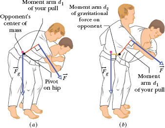
To throw an 80 kg opponent with a basic judo hip throw, you intend to pull his uniform with a force ![]() and a moment arm d1 = 0.30 m from a pivot point (rotation axis) on your right hip (Fig. 10-19). You wish to rotate him about the pivot point with an angular acceleration α of −6.0 rad/s2—that is, with an angular acceleration that is clockwise in the figure. Assume that his rotational inertia I relative to the pivot point is 15 kg · m2.
and a moment arm d1 = 0.30 m from a pivot point (rotation axis) on your right hip (Fig. 10-19). You wish to rotate him about the pivot point with an angular acceleration α of −6.0 rad/s2—that is, with an angular acceleration that is clockwise in the figure. Assume that his rotational inertia I relative to the pivot point is 15 kg · m2.
(a) What must the magnitude of ![]() be if, before you throw him, you bend your opponent forward to bring his center of mass to your hip (Fig. 10-19a)?
be if, before you throw him, you bend your opponent forward to bring his center of mass to your hip (Fig. 10-19a)?
Solution: One Key Idea here is that we can relate your pull ![]() on him to the given angular acceleration α via Newton’s second law for rotation (
on him to the given angular acceleration α via Newton’s second law for rotation (![]() ). As his feet leave the floor, we can assume that only three forces act on him: your pull
). As his feet leave the floor, we can assume that only three forces act on him: your pull ![]() , a force
, a force ![]() on him from you at the pivot point (this force is not indicated in Fig. 10-19), and the gravitational force
on him from you at the pivot point (this force is not indicated in Fig. 10-19), and the gravitational force ![]() . To use
. To use ![]() , we need the corresponding three torques, each about the pivot point.
, we need the corresponding three torques, each about the pivot point.
From Eq. 10-41 (![]() = r⊥F), the torque due to your pull
= r⊥F), the torque due to your pull ![]() is equal to −d1F, where d1 is the moment arm r⊥ and the sign indicates the clockwise rotation this torque tends to cause. The torque due to
is equal to −d1F, where d1 is the moment arm r⊥ and the sign indicates the clockwise rotation this torque tends to cause. The torque due to ![]() is zero, because
is zero, because ![]() acts at the pivot point and thus has moment arm r⊥ = 0.
acts at the pivot point and thus has moment arm r⊥ = 0.
To evaluate the torque due to ![]() , we need a Key Idea from Chapter 9: We can assume that
, we need a Key Idea from Chapter 9: We can assume that ![]() acts at your opponent’s center of mass. With the center of mass at the pivot point,
acts at your opponent’s center of mass. With the center of mass at the pivot point, ![]() has moment arm r⊥ = 0 and thus the torque due to
has moment arm r⊥ = 0 and thus the torque due to ![]() is zero. Thus, the only torque on your opponent is due to your pull
is zero. Thus, the only torque on your opponent is due to your pull ![]() , and we can write
, and we can write ![]() as
as

We then find

(b) What must the magnitude of ![]() be if your opponent remains upright before you throw him, so that
be if your opponent remains upright before you throw him, so that ![]() has a moment arm d2 = 0.12 m from the pivot point (Fig. 10-19b)?
has a moment arm d2 = 0.12 m from the pivot point (Fig. 10-19b)?
Solution: The Key Ideas we need here are similar to those in (a) with one exception: Because the moment arm for ![]() is no longer zero, the torque due to
is no longer zero, the torque due to ![]() is now equal to d2mg and is positive because the torque attempts counterclockwise rotation. Now we write
is now equal to d2mg and is positive because the torque attempts counterclockwise rotation. Now we write ![]() as
as

which gives

From (a), we know that the first term on the right is equal to 300 N. Substituting this and the given data, we have

Fig. 10-19 A judo hip throw (a) correctly executed and (b) incorrectly executed.

The results indicate that you will have to pull much harder if you do not initially bend your opponent to bring his center of mass to your hip. A good judo fighter knows this lesson from physics. (An analysis of the physics of judo and aikido is given in “The Amateur Scientist” by J. Walker, Scientific American, July 1980, Vol. 243, pp. 150–161.)
Leave a Reply