All the definitions, experiments, and observations we have discussed so far can be summarized in one neat statement:
![]() Newton’s Second Law: The net force on a body is equal to the product of the body’s mass and its acceleration.
Newton’s Second Law: The net force on a body is equal to the product of the body’s mass and its acceleration.
In equation form,

This equation is simple, but we must use it cautiously. First, we must be certain about which body we are applying it to. Then ![]() must be the vector sum of all the forces that act on that body. Only forces that act on that body are to be included in the vector sum, not forces acting on other bodies that might be involved in the given situation. For example, if you are in a rugby scrum, the net force on you is the vector sum of all the pushes and pulls on your body. It does not include any push or pull on another player from you.
must be the vector sum of all the forces that act on that body. Only forces that act on that body are to be included in the vector sum, not forces acting on other bodies that might be involved in the given situation. For example, if you are in a rugby scrum, the net force on you is the vector sum of all the pushes and pulls on your body. It does not include any push or pull on another player from you.
Like other vector equations, Eq. 5-1 is equivalent to three component equations, one for each axis of an xyz coordinate system:

Each of these equations relates the net force component along an axis to the acceleration along that same axis. For example, the first equation tells us that the sum of all the force components along the x axis causes the x component ax of the body’s acceleration, but causes no acceleration in the y and z directions. Turned around, the acceleration component ax is caused only by the sum of the force components along the x axis. In general,
![]() The acceleration component along a given axis is caused only by the sum of the force components along that same axis, and not by force components along any other axis.
The acceleration component along a given axis is caused only by the sum of the force components along that same axis, and not by force components along any other axis.
Equation 5-1 tells us that if the net force on a body is zero, the body’s acceleration ![]() = 0. If the body is at rest, it stays at rest; if it is moving, it continues to move at constant velocity. In such cases, any forces on the body balance one another, and both the forces and the body are said to be in equilibrium. Commonly, the forces are also said to cancel one another, but the term “cancel” is tricky. It does not mean that the forces cease to exist (canceling forces is not like canceling dinner reservations). The forces still act on the body.
= 0. If the body is at rest, it stays at rest; if it is moving, it continues to move at constant velocity. In such cases, any forces on the body balance one another, and both the forces and the body are said to be in equilibrium. Commonly, the forces are also said to cancel one another, but the term “cancel” is tricky. It does not mean that the forces cease to exist (canceling forces is not like canceling dinner reservations). The forces still act on the body.
For SI units, Eq. 5-1 tells us that

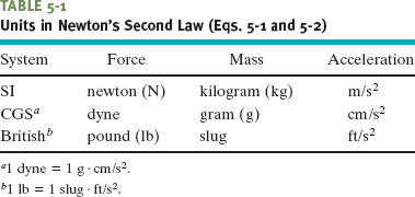
Some force units in other systems of units are given in Table 5-1 and Appendix D.
To solve problems with Newton’s second law, we often draw a free-body diagram in which the only body shown is the one for which we are summing forces. A sketch of the body itself is preferred by some teachers but, to save space in these chapters, we shall usually represent the body with a dot. Also, each force on the body is drawn as a vector arrow with its tail on the body. A coordinate system is usually included, and the acceleration of the body is sometimes shown with a vector arrow (labeled as an acceleration).
A system consists of one or more bodies, and any force on the bodies inside the system from bodies outside the system is called an external force. If the bodies making up a system are rigidly connected to one another, we can treat the system as one composite body, and the net force ![]() on it is the vector sum of all external forces. (We do not include internal forces—that is, forces between two bodies inside the system.) For example, a connected railroad engine and car form a system. If, say, a tow line pulls on the front of the engine, the force due to the tow line acts on the whole engine–car system. Just as for a single body, we can relate the net external force on a system to its acceleration with Newton’s second law,
on it is the vector sum of all external forces. (We do not include internal forces—that is, forces between two bodies inside the system.) For example, a connected railroad engine and car form a system. If, say, a tow line pulls on the front of the engine, the force due to the tow line acts on the whole engine–car system. Just as for a single body, we can relate the net external force on a system to its acceleration with Newton’s second law, ![]() , where m is the total mass of the system.
, where m is the total mass of the system.
![]() CHECK POINT 2 The figure here shows two horizontal forces acting on a block on a frictionless floor. If a third horizontal force
CHECK POINT 2 The figure here shows two horizontal forces acting on a block on a frictionless floor. If a third horizontal force ![]() also acts on the block, what are the magnitude and direction of
also acts on the block, what are the magnitude and direction of ![]() when the block is (a) stationary and (b) moving to the left with a constant speed of 5 m/s?
when the block is (a) stationary and (b) moving to the left with a constant speed of 5 m/s?

In Figs. 5-3a to c, one or two forces act on a puck that moves over frictionless ice along an x axis, in one-dimensional motion. The puck’s mass is m = 0.20 kg. Forces ![]() and
and ![]() are directed along the axis and have magnitudes F1 = 4.0 N and F2 = 2.0 N. Force
are directed along the axis and have magnitudes F1 = 4.0 N and F2 = 2.0 N. Force ![]() is directed at angle θ = 30° and has magnitude F3 = 1.0 N. In each situation, what is the acceleration of the puck?
is directed at angle θ = 30° and has magnitude F3 = 1.0 N. In each situation, what is the acceleration of the puck?
Solution: The Key Idea in each situation is that we can relate the acceleration ![]() to the net force
to the net force ![]() acting on the puck with Newton’s second law,
acting on the puck with Newton’s second law, ![]() . However, because the motion is along only the x axis, we can simplify each situation by writing the second law for x components only:
. However, because the motion is along only the x axis, we can simplify each situation by writing the second law for x components only:

The free-body diagrams for the three situations are given in Figs. 5-3d to f with the puck represented by a dot.
For Fig. 5-3d, where only one horizontal force acts, Eq. 5-4 gives us

which, with given data, yields

The positive answer indicates that the acceleration is in the positive direction of the x axis.
In Fig. 5-3e, two horizontal forces act on the puck, ![]() in the positive direction of x and
in the positive direction of x and ![]() in the negative direction. Now Eq. 5-4 gives us
in the negative direction. Now Eq. 5-4 gives us

which, with given data, yields

Thus, the net force accelerates the puck in the positive direction of the x axis.
In Fig. 5-3f, force ![]() is not directed along the direction of the puck’s acceleration; only the x component F3,x is. (Force
is not directed along the direction of the puck’s acceleration; only the x component F3,x is. (Force ![]() is two-dimensional but the motion is only one-dimensional.) Thus, we write Eq. 5-4 as
is two-dimensional but the motion is only one-dimensional.) Thus, we write Eq. 5-4 as
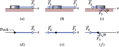
Fig. 5-3 (a)–(c) In three situations, forces act on a puck that moves along an x axis. (d)–(f) Free-body diagrams.

From the figure, we see that F3,x = F3 cos θ. Solving for the acceleration and substituting for F3,x yield

Thus, the net force accelerates the puck in the negative direction of the x axis.
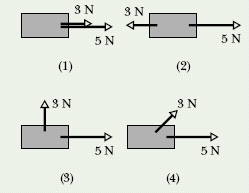
![]() CHECK POINT 3 The figure shows overhead views of four situations in which two forces accelerate the same block across a frictionless floor. Rank the situations according to the magnitudes of (a) the net force on the block and (b) the acceleration of the block, greatest first.
CHECK POINT 3 The figure shows overhead views of four situations in which two forces accelerate the same block across a frictionless floor. Rank the situations according to the magnitudes of (a) the net force on the block and (b) the acceleration of the block, greatest first.
In the overhead view of Fig. 5-4a, a 2.0 kg cookie tin is accelerated at 3.0 m/s2 in the direction shown by ![]() , over a frictionless horizontal surface. The acceleration is caused by three horizontal forces, only two of which are shown:
, over a frictionless horizontal surface. The acceleration is caused by three horizontal forces, only two of which are shown: ![]() of magnitude 10 N and
of magnitude 10 N and ![]() of magnitude 20 N. What is the third force
of magnitude 20 N. What is the third force ![]() in unit-vector notation and in magnitude-angle notation?
in unit-vector notation and in magnitude-angle notation?
Solution: One Key Idea here is that the net force ![]() on the tin is the sum of the three forces and is related to the acceleration
on the tin is the sum of the three forces and is related to the acceleration ![]() via Newton’s second law
via Newton’s second law ![]() . Thus,
. Thus,

which gives us

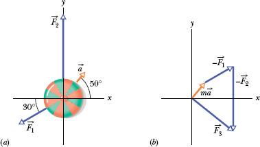
Fig. 5-4 (a) An overhead view of two of three horizontal forces that act on a cookie tin, resulting in acceleration ![]() .
. ![]() is not shown. (b) An arrangement of vectors
is not shown. (b) An arrangement of vectors ![]() , and −
, and −![]() to find force
to find force ![]() .
.
A second Key Idea is that this is a two-dimensional problem; so we cannot find ![]() merely by substituting the magnitudes for the vector quantities on the right side of Eq. 5-5. Instead, we must vectorially add
merely by substituting the magnitudes for the vector quantities on the right side of Eq. 5-5. Instead, we must vectorially add ![]() (the reverse of
(the reverse of ![]() ), and −
), and −![]() (the reverse of
(the reverse of ![]() ), as shown in Fig. 5-4b. This addition can be done directly on a vector-capable calculator because we know both magnitude and angle for all three vectors. However, here we shall evaluate the right side of Eq. 5-5 in terms of components, first along the x axis and then along the y axis.
), as shown in Fig. 5-4b. This addition can be done directly on a vector-capable calculator because we know both magnitude and angle for all three vectors. However, here we shall evaluate the right side of Eq. 5-5 in terms of components, first along the x axis and then along the y axis.
Along the x axis we have

Then, substituting known data, we find

Similarly, along the y axis we find

Thus, in unit-vector notation, we have

We can now use a vector-capable calculator to get the magnitude and the angle of ![]() . We can also use Eq. 3-6 to obtain the magnitude and the angle (from the positive direction of the x axis) as
. We can also use Eq. 3-6 to obtain the magnitude and the angle (from the positive direction of the x axis) as

In a two-dimensional tug-of-war, Alex, Betty, and Charles pull horizontally on an automobile tire at the angles shown in the overhead view of Fig. 5-5a. The tire remains stationary in spite of the three pulls. Alex pulls with force ![]() of magnitude 220 N, and Charles pulls with force
of magnitude 220 N, and Charles pulls with force ![]() of magnitude 170 N. The direction of
of magnitude 170 N. The direction of ![]() is not given. What is the magnitude of Betty’s force
is not given. What is the magnitude of Betty’s force ![]() ?
?
Solution: Because the three forces do not accelerate the tire, its acceleration is ![]() = 0 (that is, the forces are in equilibrium). The Key Idea here is that we can relate that acceleration to the net force
= 0 (that is, the forces are in equilibrium). The Key Idea here is that we can relate that acceleration to the net force ![]() on the tire with Newton’s second law (
on the tire with Newton’s second law (![]() ), which we can write as
), which we can write as

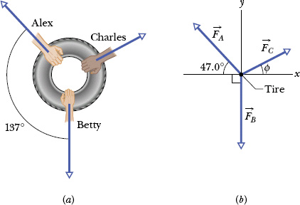
Fig. 5-5 (a) An overhead view of three people pulling on a tire. (b) A free-body diagram for the tire.
The free-body diagram for the tire is shown in Fig. 5-5b, where we have conveniently centered a coordinate system on the tire and assigned ![]() to the angle of
to the angle of ![]() .
.
We want to solve for the magnitude of ![]() . Although we know both magnitude and direction for
. Although we know both magnitude and direction for ![]() , we know only the magnitude of
, we know only the magnitude of ![]() and not its direction. Thus, with unknowns on both sides of Eq. 5-6, we cannot directly solve it on a vector-capable calculator. Instead we must rewrite Eq. 5-6 in terms of components for either the x or the y axis. Since
and not its direction. Thus, with unknowns on both sides of Eq. 5-6, we cannot directly solve it on a vector-capable calculator. Instead we must rewrite Eq. 5-6 in terms of components for either the x or the y axis. Since ![]() is directed along the y axis, we choose that axis and write
is directed along the y axis, we choose that axis and write

Evaluating these components with their angles and using the angle 133° (= 180° − 47.0°) for ![]() , we obtain
, we obtain

which, with the given data for the magnitudes, yields

However, we do not know ![]() .
.
We can find it by rewriting Eq. 5-6 for the x axis as

and then as

which gives us

Inserting this into Eq. 5-7, we find

TACTIC 1 : Dimensions and Vectors
Many students fail to grasp the second Key Idea in Sample Problem 5-2, and that failure haunts them through the rest of this book. When you are dealing with forces, you cannot just add or subtract their magnitudes to find their net force unless they happen to be directed along the same axis. If they are not, you must use vector addition, either by means of a vector-capable calculator or by finding components along axes, as is done in Sample Problem 5-2.
TACTIC 2 : Reading Force Problems
Read the problem statement several times until you have a good mental picture of what the situation is, what data are given, and what is requested. If you know what the problem is about but don’t know what to do next, put the problem aside and reread the text. If you are hazy about Newton’s second law, reread that section. Study the sample problems. And remember that solving physics problems (like repairing cars and designing computer chips) takes training—you were not born with the ability.
TACTIC 3 : Draw Two Types of Figures
You may need two figures. One is a rough sketch of the actual situation. When you draw the forces, place the tail of each force vector either on the boundary of or within the body on which that force acts. The other figure is a free-body diagram: the forces on a single body are drawn, with the body represented by a dot or a sketch. Place the tail of each force vector on the dot or sketch.
TACTIC 4 : What Is Your System?
If you are using Newton’s second law, you must know what body or system you are applying it to. In Sample Problem 5-1 it is the puck (not the ice). In Sample Problem 5-2, it is the cookie tin. In Sample Problem 5-3, it is the tire (not the people).
TACTIC 5 : Choose Your Axes Wisely
In Sample Problem 5-3, we saved a lot of work by choosing one of our coordinate axes to coincide with one of the forces (the y axis with ![]() ).
).
Leave a Reply