The mechanical energy Emec of a system is the sum of its potential energy U and the kinetic energy K of the objects within it:

In this section, we examine what happens to this mechanical energy when only conservative forces cause energy transfers within the system — that is, when frictional and drag forces do not act on the objects in the system. Also, we shall assume that the system is isolated from its environment; that is, no external force from an object outside the system causes energy changes inside the system.
When a conservative force does work W on an object within the system, that force transfers energy between kinetic energy K of the object and potential energy U of the system. From Eq. 7-10, the change ΔK in kinetic energy is

and from Eq. 8-1, the change ΔU in potential energy is

Combining Eqs. 8-13 and 8-14, we find that

In words, one of these energies increases exactly as much as the other decreases.
We can rewrite Eq. 8-15 as

where the subscripts refer to two different instants and thus to two different arrangements of the objects in the system. Rearranging Eq. 8-16 yields

In words, this equation says:

when the system is isolated and only conservative forces act on the objects in the system. In other words:
![]() In an isolated system where only conservative forces cause energy changes, the kinetic energy and potential energy can change, but their sum, the mechanical energy Emec of the system, cannot change.
In an isolated system where only conservative forces cause energy changes, the kinetic energy and potential energy can change, but their sum, the mechanical energy Emec of the system, cannot change.
This result is called the principle of conservation of mechanical energy. (Now you can see where conservative forces got their name.) With the aid of Eq. 8-15, we can write this principle in one more form, as

The principle of conservation of mechanical energy allows us to solve problems that would be quite difficult to solve using only Newton’s laws:
![]() When the mechanical energy of a system is conserved, we can relate the sum of kinetic energy and potential energy at one instant to that at another instant without considering the intermediate motion and without finding the work done by the forces involved.
When the mechanical energy of a system is conserved, we can relate the sum of kinetic energy and potential energy at one instant to that at another instant without considering the intermediate motion and without finding the work done by the forces involved.
Figure 8-7 shows an example in which the principle of conservation of mechanical energy can be applied: As a pendulum swings, the energy of the pendulum – Earth system is transferred back and forth between kinetic energy K and gravitational potential energy U, with the sum K + U being constant. If we know the gravitational potential energy when the pendulum bob is at its highest point (Fig. 8-7c), Eq. 8-17 gives us the kinetic energy of the bob at the lowest point (Fig. 8-7e).
For example, let us choose the lowest point as the reference point, with the gravitational potential energy U2 = 0. Suppose then that the potential energy at the highest point is U1 = 20 J relative to the reference point. Because the bob momentarily stops at its highest point, the kinetic energy there is K1 = 0. Substituting these values into Eq. 8-17 gives us the kinetic energy K2 at the lowest point:
K2 + 0 = 0 + 20 J or K2 = 20 J.
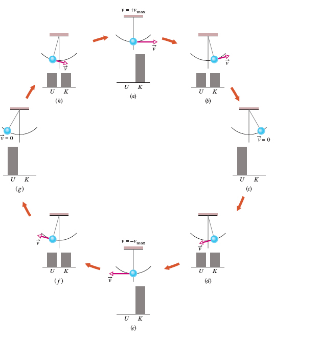
Fig. 8-7 A pendulum, with its mass concentrated in a bob at the lower end, swings back and forth. One full cycle of the motion is shown. During the cycle the values of the potential and kinetic energies of the pendulum–Earth system vary as the bob rises and falls, but the mechanical energy Emec of the system remains constant. The energy Emec can be described as continuously shifting between the kinetic and potential forms. In stages (a) and (e), all the energy is kinetic energy. The bob then has its greatest speed and is at its lowest point. In stages (c) and (g), all the energy is potential energy. The bob then has zero speed and is at its highest point. In stages (b), (d), (f), and (h), half the energy is kinetic energy and half is potential energy. If the swinging involved a frictional force at the point where the pendulum is attached to the ceiling, or a drag force due to the air, then Emec would not be conserved, and eventually the pendulum would stop.
Note that we get this result without considering the motion between the highest and lowest points (such as in Fig. 8-7d) and without finding the work done by any forces involved in the motion.
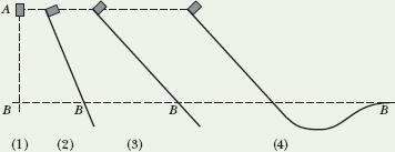
![]() CHECK POINT 3 The figure shows four situations—one in which an initially stationary block is dropped and three in which the block is allowed to slide down frictionless ramps. (a) Rank the situations according to the kinetic energy of the block at point B, greatest first. (b) Rank them according to the speed of the block at point B, greatest first.
CHECK POINT 3 The figure shows four situations—one in which an initially stationary block is dropped and three in which the block is allowed to slide down frictionless ramps. (a) Rank the situations according to the kinetic energy of the block at point B, greatest first. (b) Rank them according to the speed of the block at point B, greatest first.
In Fig. 8-8, a child of mass m is released from rest at the top of a water slide, at height h = 8.5 m above the bottom of the slide. Assuming that the slide is frictionless because of the water on it, find the child’s speed at the bottom of the slide.
Solution: A Key Idea here is that we cannot find her speed at the bottom by using her acceleration along the slide as we might have in earlier chapters because we do not know the slope (angle) of the slide. However, because that speed is related to her kinetic energy, perhaps we can use the principle of conservation of mechanical energy to get the speed. Then we would not need to know the slope. A second Key Idea is that mechanical energy is conserved in a system if the system is isolated and if only conservative forces cause energy transfers within it. Let’s check.
Forces: Two forces act on the child. The gravitational force, a conservative force, does work on her. The normal force on her from the slide does no work because its direction at any point during the descent is always perpendicular to the direction in which the child moves.
System: Because the only force doing work on the child is the gravitational force, we choose the child–Earth system as our system, which we can take to be isolated.
Thus, we have only a conservative force doing work in an isolated system, so we can use the principle of conservation of mechanical energy. Let the mechanical energy be Emec,t when the child is at the top of the slide and Emec,b when she is at the bottom. Then the conservation principle tells us
Emec,b = Emec,t.
To show both kinds of mechanical energy, we have
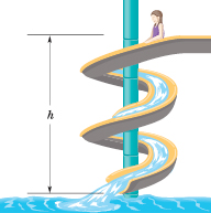
Fig. 8-8 A child slides down a water slide as she descends a height h.
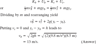
This is the same speed that the child would reach if she fell 8.5 m vertically. On an actual slide, some frictional forces would act and the child would not be moving quite so fast.
Although this problem is hard to solve directly with Newton’s laws, using conservation of mechanical energy makes the solution much easier. However, if we were asked to find the time taken for the child to reach the bottom of the slide, energy methods would be of no use; we would need to know the shape of the slide, and we would have a difficult problem.
Figure 8-9a shows a rock-climbing situation in which a leader falls from a height H above a runner (the fixed metal loop through which the rope runs) while a (lower) second climber holds fast to the rope, to limit the fall. When the falling leader reaches distance H below the runner, the rope begins to stretch. The stretch is maximum when the leader has fallen an additional distance d and has come to a stop. The force on the rope is then maximum at magnitude Fmax. That is the really dangerous part of the fall because Fmax could be large enough to snap the rope.
To calculate Fmax, we first approximate that a rope is stretched like a spring according to Hooke’s law (Eq. 7-21, Fx = − kx). For any particular rope, the spring constant k depends on (1) the length L of the rope and (2) the elasticityerope of the rope material (roughly, the material’s ability to stretch):

Here, assume the rope has a typical elasticity of erope = 20 kN and the leader has a mass of m = 80 kg. Take the positive direction of a vertical y axis to be up. Calculate Fmax for the long fall of Fig. 8-9a and the short fall of Fig. 8-9c. For which fall is the rope in more danger of snapping?
Solution: Because it stretches like a spring, a rope stores elastic potential energy due to the conservative spring force.
A Key Idea, then, is that perhaps we can apply the principle of conservation of mechanical energy between the leader’s initial position (at the start of the fall) and the leader’s lowest position (at maximum stretch of the rope). In that case, a second Key Idea is that mechanical energy is conserved in our system (leader–Earth–rope) if the system is isolated and if only conservative forces cause energy transfers within it. Let’s check.
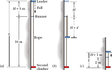
Fig. 8-9 (a) A leader located at distance L above a second climber and at distance H above a metal runner anchored to the rock wall. (b) The lowest position of the fallen leader, with the rope stretched by distance d. (c) A leader at shorter distances L and H.
Forces: The gravitational force between the leader and Earth transfers energy from gravitational potential energy to kinetic energy. Once the rope begins to stretch, the spring force transfers energy to elastic potential energy of the rope. The gravitational force and the spring-like force are both conservative.
System: The system includes both forces and all the energy transfers, and we can take it to be isolated.
Thus we can apply the principle of conservation of mechanical energy to this system. From Eq. 8-18, we can write the principle as

where ΔK is the change in the leader’s kinetic energy, ΔUg is the change in the system’s gravitational potential energy, and ΔUrope is the change in the system’s elastic potential energy. All three energy changes in Eq. 8-20 must be computed between the leader’s initial and lowest positions.
Kinetic energy: Because the leader is momentarily stationary at both points, we have ΔK = 0.
Gravitational potential energy: From Eq. 8-7, we know that ΔUg = mg Δy, where Δy is the change in the leader’s elevation during the fall. The leader falls by distance H to reach the runner, by H again to the point where the rope begins to stretch, and then by distance d during the stretching (Fig. 8-9b). So we have
ΔUg = mg Δy = mg(− 2H − d).
Elastic potential energy: At the beginning of the fall, the rope is not stretched; at the end, it is stretched by distance d. Thus, from Eq. 8-10 ![]() , the change in the elastic potential energy is
, the change in the elastic potential energy is

Inserting these three energy changes into Eq. 8-20, we obtain

This is a quadratic equation in terms of d. Its general solution (see Appendix E) is

Only the positive root gives a positive value for stretch distance d. Then, from Eq. 7-21 (Fx = − kx), the magnitude of the force on the rope is

Substituting for k from Eq. 8-19, we can next write

The quantity 2H is the distance the leader falls before the rope begins to stretch. In the long fall of Fig. 8-9a, 2H = 6.0 m and the length of the rope is L = 13 m. The weight of the leader is mg = (80 kg)(9.8 m/s2) = 784 N, and the elasticity of the rope material is erope = 20 000 N. Substituting these values into Eq. 8-21 gives us

For the short fall of Fig. 8-9c, the leader falls by only 2H = 2.0 m before the rope begins to stretch; thus, the danger of snapping the rope seems less. However, when we substitute 2H = 2.0 m and L = 3.0 m into Eq. 8-21, we find

Thus, the shorter fall here is actually more dangerous.
Skilled climbers know that the danger of snapping the rope does not depend only on the leader’s distance H above the highest runner. Rather, it depends on the ratio of 2H/L, which is known as the fall factor. To estimate the danger during a climb, a skilled climber simply estimates the fall factor; the greater its value, the greater the danger of snapping the rope. When the danger is too high, the climber anchors another runner to reduce it. The fall factor for the long fall of Fig. 8-9a is 6/13 = 0.46, and for the short fall of Fig. 8-9c it is 2/3 = 0.67. Thus Fig. 8-9c has the greater danger, and the leader should anchor another runner before going much higher.
PROBLEM-SOLVING TACTICS
TACTIC 2: Conservation of Mechanical Energy
Asking the following questions will help you to solve problems involving the principle of conservation of mechanical energy.
For what system is mechanical energy conserved? You should be able to separate your system from its environment. Imagine drawing a closed surface such that whatever is inside is your system and whatever is outside is the environment of that system. In Sample Problem 8-3 the system is the child + Earth; in Sample Problem 8-4 it is the leader + Earth + rope.
Is friction or drag present? If friction or drag is present, mechanical energy is not conserved.
Is your system isolated? The principle of conservation of mechanical energy applies only to isolated systems. That means that no external forces (forces exerted by objects outside the system) should do work on the objects in the system.
What are the initial and final states of your system? The system changes from some initial configuration to some final configuration. You apply the principle of conservation of mechanical energy by saying that Emec has the same value in both these configurations. Be very clear about what these two configurations are.
Leave a Reply