So far we have discussed two powerful conservation laws, the conservation of energy and the conservation of linear momentum. Now we meet a third law of this type, involving the conservation of angular momentum. We start from Eq. 11-29 ![]() , which is Newton’s second law in angular form. If no net external torque acts on the system, this equation becomes
, which is Newton’s second law in angular form. If no net external torque acts on the system, this equation becomes ![]() , or
, or

This result, called the law of conservation of angular momentum, can also be written as

Equations 11-32 and 11-33 tell us:
![]() If the net external torque acting on a system is zero, the angular momentum
If the net external torque acting on a system is zero, the angular momentum ![]() of the system remains constant, no matter what changes take place within the system.
of the system remains constant, no matter what changes take place within the system.

Fig. 11-17 (a) The student has a relatively large rotational inertia about the rotation axis and a relatively small angular speed. (b) By decreasing his rotational inertia, the student automatically increases his angular speed. The angular momentum ![]() of the rotating system remains unchanged.
of the rotating system remains unchanged.
Equations 11-32 and 11-33 are vector equations; as such, they are equivalent to three component equations corresponding to the conservation of angular momentum in three mutually perpendicular directions. Depending on the torques acting on a system, the angular momentum of the system might be conserved in only one or two directions but not in all directions:
![]() If the component of the net external torque on a system along a certain axis is zero, then the component of the angular momentum of the system along that axis cannot change, no matter what changes take place within the system.
If the component of the net external torque on a system along a certain axis is zero, then the component of the angular momentum of the system along that axis cannot change, no matter what changes take place within the system.
We can apply this law to the isolated body in Fig. 11-15, which rotates around the z axis. Suppose that the initially rigid body somehow redistributes its mass relative to that rotation axis, changing its rotational inertia about that axis. Equations 11-32 and 11-33 state that the angular momentum of the body cannot change. Substituting Eq. 11-31 (for the angular momentum along the rotational axis) into Eq. 11-33, we write this conservation law as

Here the subscripts refer to the values of the rotational inertia I and angular speed ω before and after the redistribution of mass.
Like the other two conservation laws that we have discussed, Eqs. 11-32 and 11-33 hold beyond the limitations of Newtonian mechanics. They hold for particles whose speeds approach that of light (where the theory of special relativity reigns), and they remain true in the world of subatomic particles (where quantum physics reigns). No exceptions to the law of conservation of angular momentum have ever been found.
We now discuss four examples involving this law.
1. The spinning volunteer Figure 11-17 shows a student seated on a stool that can rotate freely about a vertical axis. The student, who has been set into rotation at a modest initial angular speed ωi, holds two dumbbells in his outstretched hands. His angular momentum vector ![]() lies along the vertical rotation axis, pointing upward.
lies along the vertical rotation axis, pointing upward.
The instructor now asks the student to pull in his arms; this action reduces his rotational inertia from its initial value Ii to a smaller value If because he moves mass closer to the rotation axis. His rate of rotation increases markedly, from ωi to ωf. The student can then slow down by extending his arms once more, moving the dumbbells outward.
No net external torque acts on the system consisting of the student, stool, and dumbbells. Thus, the angular momentum of that system about the rotation axis must remain constant, no matter how the student maneuvers the dumbbells. In Fig. 11-17a, the student’s angular speed ωi is relatively low and his rotational inertia Ii is relatively high. According to Eq. 11-34, his angular speed in Fig. 11-17b must be greater to compensate for the decreased If.
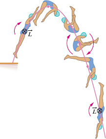
2. The springboard diver Figure 11-18 shows a diver doing a forward one-and-a-half-somersault dive. As you should expect, her center of mass follows a parabolic path. She leaves the springboard with a definite angular momentum ![]() about an axis through her center of mass, represented by a vector pointing into the plane of Fig. 11-18, perpendicular to the page. When she is in the air, no net external torque acts on her about her center of mass, so her angular momentum about her center of mass cannot change. By pulling her arms and legs into the closed tuck position, she can considerably reduce her rotational inertia about the same axis and thus, according to Eq. 11-34, considerably increase her angular speed. Pulling out of the tuck position (into the open layout position) at the end of the dive increases her rotational inertia and thus slows her rotation rate so she can enter the water with little splash. Even in a more complicated dive involving both twisting and somersaulting, the angular momentum of the diver must be conserved, in both magnitude and direction, throughout the dive.
about an axis through her center of mass, represented by a vector pointing into the plane of Fig. 11-18, perpendicular to the page. When she is in the air, no net external torque acts on her about her center of mass, so her angular momentum about her center of mass cannot change. By pulling her arms and legs into the closed tuck position, she can considerably reduce her rotational inertia about the same axis and thus, according to Eq. 11-34, considerably increase her angular speed. Pulling out of the tuck position (into the open layout position) at the end of the dive increases her rotational inertia and thus slows her rotation rate so she can enter the water with little splash. Even in a more complicated dive involving both twisting and somersaulting, the angular momentum of the diver must be conserved, in both magnitude and direction, throughout the dive.

Fig. 11-18 The diver’s angular momentum ![]() is constant throughout the dive, being represented by the tail ⊗ of an arrow that is perpendicular to the plane of the figure. Note also that her center of mass (see the dots) follows a parabolic path.
is constant throughout the dive, being represented by the tail ⊗ of an arrow that is perpendicular to the plane of the figure. Note also that her center of mass (see the dots) follows a parabolic path.
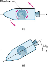
3. Spacecraft orientation Figure 11-19, which represents a spacecraft with a rigidly mounted flywheel, suggests a scheme (albeit crude) for orientation control. The spacecraft + flywheel form an isolated system. Therefore, if the system’s total angular momentum ![]() is zero because neither spacecraft nor flywheel is turning, it must remain zero (as long as the system remains isolated).
is zero because neither spacecraft nor flywheel is turning, it must remain zero (as long as the system remains isolated).
To change the orientation of the spacecraft, the flywheel is made to rotate (Fig. 11-19a). The spacecraft will start to rotate in the opposite direction to maintain the system’s angular momentum at zero. When the flywheel is then brought to rest, the spacecraft will also stop rotating but will have changed its orientation (Fig. 11-19b). Throughout, the angular momentum of the system spacecraft + flywheel never differs from zero.
Interestingly, the spacecraft Voyager 2, on its 1986 flyby of the planet Uranus, was set into unwanted rotation by this flywheel effect every time its tape recorder was turned on at high speed. The ground staff at the Jet Propulsion Laboratory had to program the onboard computer to turn on counteracting thruster jets every time the tape recorder was turned on or off.
4. The incredible shrinking star When the nuclear fire in the core of a star burns low, the star may eventually begin to collapse, building up pressure in its interior. The collapse may go so far as to reduce the radius of the star from something like that of the Sun to the incredibly small value of a few kilometers. The star then becomes a neutron star—its material has been compressed to an incredibly dense gas of neutrons.
During this shrinking process, the star is an isolated system and its angular momentum ![]() cannot change. Because its rotational inertia is greatly reduced, its angular speed is correspondingly greatly increased, to as much as 600 to 800 revolutions per second. For comparison, the Sun, a typical star, rotates at about one revolution per month.
cannot change. Because its rotational inertia is greatly reduced, its angular speed is correspondingly greatly increased, to as much as 600 to 800 revolutions per second. For comparison, the Sun, a typical star, rotates at about one revolution per month.
![]() CHECK POINT 7 A rhinoceros beetle rides the rim of a small disk that rotates like a merry-go-round. If the beetle crawls toward the center of the disk, do the following (each relative to the central axis) increase, decrease, or remain the same for the beetle–disk system: (a) rotational inertia, (b) angular momentum, and (c) angular speed?
CHECK POINT 7 A rhinoceros beetle rides the rim of a small disk that rotates like a merry-go-round. If the beetle crawls toward the center of the disk, do the following (each relative to the central axis) increase, decrease, or remain the same for the beetle–disk system: (a) rotational inertia, (b) angular momentum, and (c) angular speed?

Fig. 11-19 (a) An idealized spacecraft containing a flywheel. If the flywheel is made to rotate clockwise as shown, the spacecraft will rotate counterclockwise. (b) When the flywheel is braked to a stop, the spacecraft will also stop rotating but will be reoriented by the angle Δθsc.
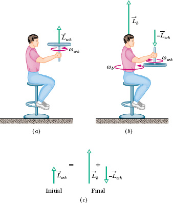
Figure 11-20a shows a student, again sitting on a stool that can rotate freely about a vertical axis. The student, initially at rest, is holding a bicycle wheel whose rim is loaded with lead and whose rotational inertia Iwh about its central axis is 1.2kg · m2. The wheel is rotating at an angular speed ωwh of 3.9 rev/s; as seen from overhead, the rotation is counterclockwise. The axis of the wheel is vertical, and the angular momentum ![]() of the wheel points vertically upward. The student now inverts the wheel (Fig. 11-20b) so that, as seen from overhead, it is rotating clockwise. Its angular momentum is now
of the wheel points vertically upward. The student now inverts the wheel (Fig. 11-20b) so that, as seen from overhead, it is rotating clockwise. Its angular momentum is now ![]() . The inversion results in the student, the stool, and the wheel’s center rotating together as a composite rigid body about the stool’s rotation axis, with rotational inertia Ib = 6.8 kg · m2. (The fact that the wheel is also rotating about its center does not affect the mass distribution of this composite body; thus, Ib has the same value whether or not the wheel rotates.) With what angular speed ωb and in what direction does the composite body rotate after the inversion of the wheel?
. The inversion results in the student, the stool, and the wheel’s center rotating together as a composite rigid body about the stool’s rotation axis, with rotational inertia Ib = 6.8 kg · m2. (The fact that the wheel is also rotating about its center does not affect the mass distribution of this composite body; thus, Ib has the same value whether or not the wheel rotates.) With what angular speed ωb and in what direction does the composite body rotate after the inversion of the wheel?
Solution: The Key Ideas here are these:
1. The angular speed ωb we seek is related to the final angular momentum ![]() of the composite body about the stool’s rotation axis by Eq. 11-31 (L = Iω).
of the composite body about the stool’s rotation axis by Eq. 11-31 (L = Iω).
2. The initial angular speed ωwh of the wheel is related to the angular momentum ![]() of the wheel’s rotation about its center by the same equation.
of the wheel’s rotation about its center by the same equation.
3. The vector addition of ![]() and
and ![]() gives the total angular momentum
gives the total angular momentum ![]() of the system of student, stool, and wheel.
of the system of student, stool, and wheel.
4. As the wheel is inverted, no net external torque acts on that system to change ![]() about any vertical axis. (Torques due to forces between the student and the wheel as the student inverts the wheel are internal to the system.) So, the system’s total angular momentum is conserved about any vertical axis.
about any vertical axis. (Torques due to forces between the student and the wheel as the student inverts the wheel are internal to the system.) So, the system’s total angular momentum is conserved about any vertical axis.
The conservation of ![]() is represented with vectors in Fig. 11-20c. We can also write this conservation in terms of components along a vertical axis as
is represented with vectors in Fig. 11-20c. We can also write this conservation in terms of components along a vertical axis as

where i and f refer to the initial state (before inversion of the wheel) and the final state (after inversion). Because inversion of the wheel inverted the angular momentum vector of the wheel’s rotation, we substitute −Lwh,i for Lwh,f. Then, if we set Lb,i = 0 (because the student, the stool, and the wheel’s center were initially at rest), Eq. 11-35 yields
Lb,f = 2Lwh,i.

Fig. 11-20 (a) A student holds a bicycle wheel rotating around a vertical axis. (b) The student inverts the wheel, setting himself into rotation. (c) The net angular momentum of the system must remain the same in spite of the inversion.
Using Eq. 11-31, we next substitute Ibωb for Lb,f and Iwhωwh for Lwh,i and solve for ωb, finding

This positive result tells us that the student rotates counterclockwise about the stool axis as seen from overhead. If the student wishes to stop rotating, he has only to invert the wheel once more.
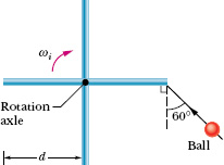
(This final sample problem of the chapter is challenging, but it is helpful because it pulls together many ideas.) In the overhead view of Fig. 11-21, four thin, uniform rods, each of mass M and length d = 0.50 m, are rigidly connected to a vertical axle to form a turnstile. The turnstile rotates clockwise about the axle, which is attached to a floor, with initial angular velocity ωi = −2.0 rad/s. A mud ball of mass ![]() and initial speed vi = 12 m/s is thrown along the path shown and sticks to the end of one rod. What is the final angular velocity ωf of the ball–turnstile system?
and initial speed vi = 12 m/s is thrown along the path shown and sticks to the end of one rod. What is the final angular velocity ωf of the ball–turnstile system?
Solution: A Key Idea here can be stated in a question-and-answer format. The question is this: Does the system have a quantity that is conserved during the collision and that involves angular velocity, so that we can solve for ωf? To answer, let us check the conservation possibilities:
1. The total kinetic energy K is not conserved, because the collision between ball and rod is completely inelastic (the ball sticks). So, some energy must be transferred from kinetic energy to other types of energy (such as thermal energy). For the same reason, total mechanical energy is not conserved.

Fig. 11-21 An overhead view of four rigidly connected rods rotating freely around a central axle, and the path a mud ball takes to stick onto one of the rods.
2. The total linear momentum ![]() is also not conserved, because during the collision an external force acts on the turnstile at the attachment of the axle to the floor. (This is the force that keeps the turnstile from moving across the floor when it is hit by the mud ball.)
is also not conserved, because during the collision an external force acts on the turnstile at the attachment of the axle to the floor. (This is the force that keeps the turnstile from moving across the floor when it is hit by the mud ball.)
3. The total angular momentum ![]() of the system about the axle is conserved because there is no net external torque to change
of the system about the axle is conserved because there is no net external torque to change ![]() . (The forces in the collision produce only internal torques; the external force on the turnstile acts at the axle, has zero moment arm, and thus does not produce an external torque.)
. (The forces in the collision produce only internal torques; the external force on the turnstile acts at the axle, has zero moment arm, and thus does not produce an external torque.)
We can write the conservation of the system’s total angular momentum (Lf = Li) about the axle as

where ts stands for “turnstile.” The final angular velocity ωf is contained in the terms Lts,f and Lball,f because those final angular momenta depend on how fast the turnstile and ball are rotating. To find ωf, we consider first the turnstile and then the ball, and then we return to Eq. 11-36.
Turnstile: The Key Idea here is that, because the turnstile is a rotating rigid object, Eq. 11-31 (L = Iω) gives its angular momentum. Thus, we can write its final and initial angular momenta about the axle as

Because the turnstile consists of four rods, each rotating around an end, the rotational inertia Its of the turnstile is four times the rotational inertia Irod of each rod about its end. From Table 10-2e, we know that the rotational inertia Icom of a rod about its center is ![]() , where M is its mass and d is its length. To get Irod we use the parallel-axis theorem of Eq. 10-36 (I = Icom + Mh2). Here the perpendicular distance h is d/2. Thus, we find
, where M is its mass and d is its length. To get Irod we use the parallel-axis theorem of Eq. 10-36 (I = Icom + Mh2). Here the perpendicular distance h is d/2. Thus, we find

With four rods in the turnstile, we then have

Ball: Before the collision, the ball is like a particle moving along a straight line, as in Fig. 11-12. So, to find the ball’s initial angular momentum Lball,i about the axle, we can use any of Eqs. 11-18 through 11-21, but Eq. 11-20 (ℓ = rmv⊥) is easiest. Here ℓ is Lball,i; just before the ball hits, its radial distance r from the axle is d and the component v⊥ of the ball’s velocity perpendicular to r is vi cos 60°.
To give a sign to this angular momentum, we mentally draw a position vector from the turnstile’s axle to the ball. As the ball approaches the turnstile, this position vector rotates counterclockwise about the axle, so the ball’s angular momentum is a positive quantity. We can now rewrite ℓ = rmv⊥ as

After the collision, the ball is like a particle rotating in a circle of radius d. So, from Eq. 10-33 ![]() , we have Iball = md2 about the axle. Then from Eq. 11-31 (L = Iω), we can write the final angular momentum of the ball about the axle as
, we have Iball = md2 about the axle. Then from Eq. 11-31 (L = Iω), we can write the final angular momentum of the ball about the axle as

Return to Eq. 11-36: Substituting from Eqs. 11-37 through 11-40 into Eq. 11-36, we have

Substituting M = 3m and solving for ωf, we find

Thus, the turnstile is now turning counterclockwise.
Leave a Reply