If a rigid body consists of a few particles, we can calculate its rotational inertia about a given rotation axis with Eq. 10-33 ![]() that is, we can find the product mr2 for each particle and then sum the products. (Recall that r is the perpendicular distance a particle is from the given rotation axis.)
that is, we can find the product mr2 for each particle and then sum the products. (Recall that r is the perpendicular distance a particle is from the given rotation axis.)
If a rigid body consists of a great many adjacent particles (it is continuous, like a Frisbee), using Eq. 10-33 would require a computer. Thus, instead, we replace the sum in Eq. 10-33 with an integral and define the rotational inertia of the body as

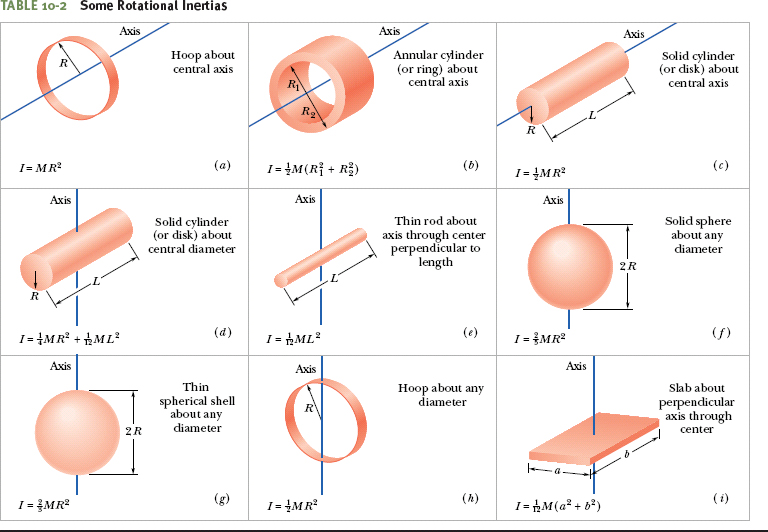
Table 10-2 gives the results of such integration for nine common body shapes and the indicated axes of rotation.
Parallel-Axis Theorem
Suppose we want to find the rotational inertia I of a body of mass M about a given axis. In principle, we can always find I with the integration of Eq. 10-35. However, there is a shortcut if we happen to already know the rotational inertia Icom of the body about a parallel axis that extends through the body’s center of mass. Let h be the perpendicular distance between the given axis and the axis through the center of mass (remember these two axes must be parallel). Then the rotational inertia I about the given axis is

This equation is known as the parallel-axis theorem. We shall now prove it and then put it to use in Checkpoint 5 and Sample Problem 10-5.
Proof of the Parallel-Axis Theorem
Let O be the center of mass of the arbitrarily shaped body shown in cross section in Fig. 10-12. Place the origin of the coordinates at O. Consider an axis through O perpendicular to the plane of the figure, and another axis through point P parallel to the first axis. Let the x and y coordinates of P be a and b.
Let dm be a mass element with the general coordinates x and y. The rotational inertia of the body about the axis through P is then, from Eq. 10-35,

which we can rearrange as

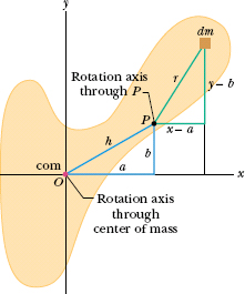
Fig. 10-12 A rigid body in cross section, with its center of mass at O. The parallel-axis theorem (Eq. 10-36) relates the rotational inertia of the body about an axis through O to that about a parallel axis through a point such as P, a distance h from the body’s center of mass. Both axes are perpendicular to the plane of the figure.
From the definition of the center of mass (Eq. 9-9), the middle two integrals of Eq. 10-37 give the coordinates of the center of mass (multiplied by a constant) and thus must each be zero. Because x2 + y2 is equal to R2, where R is the distance from O to dm, the first integral is simply Icom, the rotational inertia of the body about an axis through its center of mass. Inspection of Fig. 10-12 shows that the last term in Eq. 10-37 is Mh2, where M is the body’s total mass. Thus, Eq. 10-37 reduces to Eq. 10-36, which is the relation that we set out to prove.
![]() CHECK POINT 5 The figure shows a book-like object (one side is longer than the other) and four choices of rotation axes, all perpendicular to the face of the object. Rank the choices according to the rotational inertia of the object about the axis, greatest first.
CHECK POINT 5 The figure shows a book-like object (one side is longer than the other) and four choices of rotation axes, all perpendicular to the face of the object. Rank the choices according to the rotational inertia of the object about the axis, greatest first.
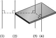
Figure 10-13a shows a rigid body consisting of two particles of mass m connected by a rod of length L and negligible mass.
(a) What is the rotational inertia Icom about an axis through the center of mass, perpendicular to the rod as shown?
Solution: The Key Idea is that because we have only two particles with mass, we can find the body’s rotational inertia Icom by using Eq. 10-33 rather than by integration. For the two particles, each at perpendicular distance ![]() L from the rotation axis, we have
L from the rotation axis, we have

(b) What is the rotational inertia I of the body about an axis through the left end of the rod and parallel to the first axis (Fig. 10-13b)?
Solution: This situation is simple enough that we can find I using either of two Key Ideas. The first is identical to the one we used in (a). The only difference here is that the perpendicular distance ri is zero for the particle on the left and L for the particle on the right. Now Eq. 10-33 gives us

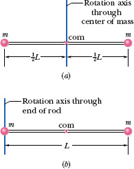
Fig. 10-13 A rigid body consisting of two particles of mass m joined by a rod of negligible mass.
The second Key Idea provides a more powerful technique: Because we already know Icom about an axis through the center of mass and because the axis here is parallel to that “com axis,” we can apply the parallel-axis theorem (Eq. 10-36). We find

Figure 10-14 shows a thin, uniform rod of mass M and length L, on an x axis with the origin at the rod’s center.
(a) What is the rotational inertia of the rod about the perpendicular rotation axis through the center?
Solution: One Key Idea is that, because the rod is uniform, its center of mass is at its center. Therefore, we are looking for Icom. A second Key Idea is that, because the rod is a continuous object, we must use the integral of Eq. 10-35,

to find the rotational inertia. However, we want to integrate with respect to coordinate x (not mass m as indicated in the integral), so we must relate the mass dm of an element of the rod to its length dx along the rod. (Such an element is shown in Fig. 10-14.) Because the rod is uniform, the ratio of mass to length is the same for all the elements and for the rod as a whole. Thus, we can write
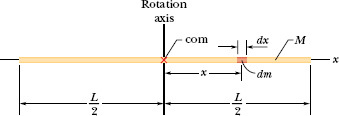
Fig. 10-14 A uniform rod of length L and mass M. An element of mass dm and length dx is represented.

or

We can now substitute this result for dm and x for r in Eq. 10-38. Then we integrate from end to end of the rod (from x = −L/2 to x = L/2) to include all the elements. We find

This agrees with the result given in Table 10-2e.
(b) What is the rod’s rotational inertia I about a new rotation axis that is perpendicular to the rod and through the left end?
Solution: Here is the more difficult of two ways to solve for I: We use the same Key Ideas as previously but this time shift the origin of the x axis to the left end of the rod and then integrate from x = 0 to x = L. Doing so, we find

The easier way is to use another Key Idea: If we place the axis at the rod’s end so that it is parallel to the axis through the center of mass, then we can use the parallel-axis theorem (Eq. 10-36). We know from part (a) that Icom is ![]() . From Fig. 10-14, the perpendicular distance h between the new rotation axis and the center of mass is
. From Fig. 10-14, the perpendicular distance h between the new rotation axis and the center of mass is ![]() L. Equation 10-36 then gives us
L. Equation 10-36 then gives us

Actually, this result holds for any axis through the left or right end that is perpendicular to the rod, whether it is parallel to the axis shown in Fig. 10-14 or not.
Large machine components that undergo prolonged, high-speed rotation are first examined for the possibility of failure in a spin test system. In this system, a component is spun up (brought up to high speed) while inside a cylindrical arrangement of lead bricks and containment liner, all within a steel shell that is closed by a lid clamped into place. If the rotation causes the component to shatter, the soft lead bricks are supposed to catch the pieces for later analysis.
In early 1985, Test Devices, Inc. (www.testdevices.com) was spin testing a sample of a solid steel rotor (a disk) of mass M = 272 kg and radius R = 38.0 cm. When the sample reached an angular speed ω of 14 000 rev/min, the test engineers heard a dull thump from the test system, which was located one floor down and one room over from them. Investigating, they found that lead bricks had been thrown out in the hallway leading to the test room, a door to the room had been hurled into the adjacent parking lot, one lead brick had shot from the test site through the wall of a neighbor’s kitchen, the structural beams of the test building had been damaged, the concrete floor beneath the spin chamber had been shoved downward by about 0.5 cm, and the 900 kg lid had been blown upward through the ceiling and had then crashed back onto the test equipment (Fig. 10-15). The exploding pieces had not penetrated the room of the test engineers only by luck.
How much energy was released in the explosion of the rotor?
Solution: The Key Idea here is that this released energy was equal to the rotational kinetic energy K of the rotor just as it reached the angular speed of 14 000 rev/min. We can find K with Eq. 10-34 ![]() , but first we need an expression for the rotational inertia I. Because the rotor was a disk that rotated like a merry-go-round, I is given by the expression in
, but first we need an expression for the rotational inertia I. Because the rotor was a disk that rotated like a merry-go-round, I is given by the expression in
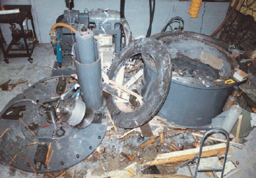
Fig. 10-15 Some of the destruction caused by the explosion of a rapidly rotating steel disk.
Table 10-2c ![]() Thus, we have
Thus, we have

The angular speed of the rotor was

Now we can use Eq. 10-34 to write

Being near this explosion was like being near an exploding bomb.
Leave a Reply