A metal electrode in an electrolyte solution is typically charged, even at equilibrium. Excess charge is present on the outer surface of the electrode, adjacent to the electrode–electrolyte interface. The amount of charge in the metal electrode is a measure of the energy of the electrons in the metal and can be changed by using a power supply to force electrons into or out of the metal. Excess electrons result in higher energy of electron because electrons tend to repel each other.
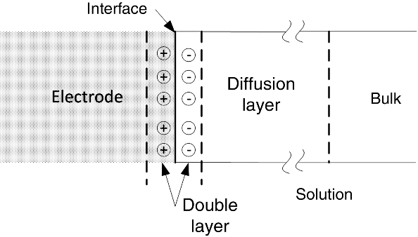
How is the electrolyte solution influenced by this excess charge? As you might expect, charged species in the electrolyte solution align themselves at the interface to balance the excess charge on the metal. The result is the formation of a double layer, as shown in Figure 3.1. Also shown in the figure is the diffusion layer; only a portion of this layer is shown because it is so much larger than the double layer and too large for a drawing of this scale (see numbers below). The solution side of the double layer is a region of nonuniform charge and, as it takes enormous energy to separate charge, it is a region where the electric field is very large. The potential difference between the metal and the solution just outside the double layer is critical to our discussion of electrode kinetics. At the open-circuit conditions we discussed in Chapter 2, where the overall current is zero, this potential difference adjusts itself through the transfer of electrons (i.e., reaction) so that the rates of the forward and reverse reactions are equal. In other words, equilibrium is achieved across the interface. The potential difference between the electrode and the solution at equilibrium provides a reference point for our discussion of kinetics later in this chapter.

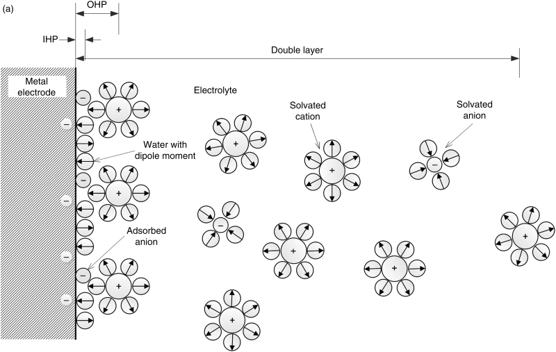
The actual structure of the double layer is more complex than the simple arrangement presented above. A more complete view, along with the common nomenclature used to describe it, is shown in Figure 3.2. Note the importance of the solvent (water in this instance) molecules. Water molecules, which are polar, surround the ions in solution to form a hydration layer or solvent sheath. They also tend to align at the interface because of their dipole nature and the charge on the surface. The inner Helmholtz plane (IHP) is the position of the centers of ions or molecules that adsorb directly onto the electrode surface. They may experience van der Waals interactions with the surface in addition to coulombic interactions.

To adsorb directly on the surface, an ion must at least partially shed its waters of hydration. Negatively charged ions (anions) hydrate less strongly than cations and are more frequently found in the inner Helmholtz plane. They can even adsorb to a negatively charged surface. As a general rule, the weaker the solvation of an anion, the more strongly it tends to undergo specific (direct) absorption to the surface. The outer Helmholtz plane (OHP) is the plane of closest approach for solvated ions, where the solvent sheath prevents specific adsorption. Its position is defined by the radius, including the waters of hydration, of the largest solvated ions (∼0.2 nm). The last portion of the double layer is called the diffuse double layer. This layer is characterized by a balance of Brownian motion and Coulombic forces. This balance is analogous to the one introduced in Chapter 2 in the development of the Debye–Hückel theory for activity coefficients. Both positive and negative charges are present, and the amount of excess charge decreases gradually from the OHP to the solution side of the diffuse double layer where the solution is electrically neutral. The thickness of the diffuse double layer is characterized by the Debye length:
(3.1)
and is a function of concentration. The diffuse part of the double layer is important at low concentrations and has a thickness of about 10 nm at an ionic strength of 1 mM. The diffuse part of the double layer is typically not as important at concentrations used in practical electrochemical systems, but the structure of the double layer is critical to the understanding of charge transfer. In contrast to the thin diffuse double layer, the diffusion layer is on the order of 1 mm; thus, the diffusion layer is typically orders of magnitude larger than the thickness of the double layer. The potential drop from the potential of the metal (ϕm) to the potential of the solution just outside the double layer (ϕs) is also shown in Figure 3.2. For a potential difference of 1 V, the electric field is

which is quite high. There is also a capacitance associated with the separation of charge across the double layer. In fact, reference is often made to electrochemical capacitors or double-layer capacitors. The capacitance, C, is simply
(3.2)![]()
where Q is the charge on the electrode. By adjusting the potential, this charge can be changed. Here an ideally polarizable electrode is envisaged, which is an electrode where an arbitrary potential can be applied without causing a faradaic reaction to occur. Under these conditions, there is no faradaic reaction associated with the electrical current, only simple movement of the charges. The capacitance is discussed in more detail in Chapter 11, along with devices that take advantage of this effect. In this chapter, our focus will be on faradaic reactions, which are reactions that involve the transfer of electrons across the interface in order to change the oxidation state of at least one of the participating species. The half-cell reactions that we wrote in Chapters 1 and 2 are examples of faradaic reactions. Faraday’s law applies to faradaic reactions and relates the current to the amount of a species reacted or formed.
Leave a Reply