A conventional electrostatic capacitor consists of two conductors separated by a dielectric (electronic insulator). Energy storage is accomplished by charge separation, with positive charge accumulated on one conductor and negative on the other (see Figure 11.1a). The charge, Q, is the amount of charge on either conductor (not the sum of the two). Capacitance is defined as the charge divided by the potential difference and relates the amount of charge stored to the electrical potential required to store that charge.
The unit for capacitance is the farad, [F], which is equivalent to coulomb per volt [C·V−1]. Alternatively, we can express a differential capacitance as
This differential representation of the capacitance provides additional information and is required in situations where the capacitance, C, varies with the amount of charge. In contrast, Equation 11.1 defines the integral capacitance.
Figure 11.1a shows a conventional parallel plate capacitor consisting of two conductive plates separated by an insulator. If the gap between the plates is a vacuum, the capacitance is constant and equal to
where d is the distance between the plates, ɛ0 is the permittivity of free space, 8.8542 × 10⁻¹² [F·m−1], and A is the area of the plates. The electrical symbol for this capacitor is also shown in the figure. The positively charged plate is called the anode and the negatively charged plate the cathode. If the vacuum is replaced by a dielectric material, the capacitance is proportional to the dielectric constant, which is the ratio of the permittivity of the material to the permittivity of vacuum:
(11.4)![]()
For a parallel plate capacitor using a dielectric material in place of a vacuum, Equation 11.3 is replaced with
(11.5)![]()
To this point, we have seen that the capacitance depends on the properties of the material between the conducting plates, as well as on the distance between the plates and the area available for charge storage. We have also defined both a differential and an integral capacitance, which relate the amount of charge stored to the voltage difference across the plates.
The capacitance of a device can be raised by increasing the area available for charge storage and by decreasing the thickness of the dielectric. These strategies are used in the electrolytic capacitor, the second type of capacitor, shown in Figure 11.1b. This kind of capacitor is significantly different from and not to be confused with an electrochemical double-layer capacitor. In addition to their capacitive properties, electrolytic capacitors are of particular interest because they are manufactured with electrochemical processes. As shown in Figure 11.1b, two metal foils are separated by an electrolyte. In contrast to the parallel plate capacitor, the areas of the two metal foils are enhanced by etching the surfaces. The increase in area is illustrated by the corrugations shown in Figure 11.1b. The etching takes place as the foil is passed through a chloride solution and current is applied to create small, tunnel-like pores, mostly perpendicular to the surface. The surface roughness (Chapter 3) or foil gain can be up to 100 times for low-voltage and 25 times for high-voltage electrolytic capacitors. The capacitance of the anode, however, does not result from the interface between the electrolyte and the foil; rather a forming process creates a thin metal oxide layer on the etched surface of one of the metal foils. This oxide is shown as alumina in the enlargement of the corrugation in Figure 11.1b. It is this oxide that serves the same role as that of the dielectric in the parallel plate capacitor. The increase in surface area and the use of a very thin oxide (dielectric) lead to a significant increase in capacitance over that of a parallel plate capacitor. The anode here represents one capacitor; there is by necessity a second capacitor at the other electrode, and these capacitors are in series. Therefore, some aspects of the physics of the device are not well represented by the electrical symbol in Figure 11.1b.
To form the electrolytic capacitor, the metal anode is anodized by applying a constant potential to oxidize the surface (essentially a corrosion process, see Chapter 16). The magnitude of the potential applied may be several hundred volts and is greater than that for which the device is rated so that no appreciable oxidation takes place during later operation. A higher formation potential leads to a thicker metal oxide on the surface, which increases the operating voltage of the capacitor at the expense of a lower capacitance due to decreased surface area and the thicker oxide layer. For an aluminum foil, aluminum oxide forms on the anode, and the alumina serves as the dielectric that separates the surface of the conductor from the electrolyte. Other metals are also used in practice. In operation, the majority of the potential difference occurs across the oxide layer, rather than in the electrolyte. Consequently, very high voltages are possible. As mentioned previously, the capacitance is increased through the use of a very thin oxide, on the order of 100 nm, which is much thinner than the separation that can be achieved in a conventional capacitor without developing shorts. Growth of a thicker oxide layer (still quite thin) provides a higher voltage rating but tends to close up the smaller pores that were etched; therefore, a higher voltage rating also implies a smaller foil gain. Importantly, we note that the electrolytic capacitor (Figure 11.1b) has a polarity; that is, in contrast to a parallel plate capacitor, it must be connected so that the anodized metal is electrically positive relative to the other electrode. This polarity is also shown in the electrical symbol in the figure. The adverse consequences of reversing this polarity are explored in Problem 11.3. We also note that charge is supplied by the electrolyte on the other side of the oxide; this feature is similar to that found in the EDLC, which will be discussed in the next section.
Finally, we close this introductory section by reviewing how to calculate the total capacitance for multiple capacitors that are connected either in parallel or in series. This knowledge is important for understanding EDLCs. For capacitors that are electrically combined in parallel, the total capacitance is simply the sum of the individual capacitances:
(11.6)![]()
In contrast, for capacitors that are placed electrically in series, the total capacitance is
A useful way to help understand the physics behind these relationships is by considering charge storage at a given voltage. Capacitors in parallel simply add storage capacity to the system. In contrast, the charge stored on each capacitor must be the same for capacitors in series, and there is a voltage drop across each of the capacitors, which must sum to the total voltage difference. For two identical capacitors in series, the voltage drop across each capacitor will be the same and equal to half of the total voltage difference. Thus, the total capacitance will be half that of the individual capacitors. For two capacitors of unequal capacitance in series, a larger fraction of the voltage drop will be across the capacitor with the smallest capacitance. This imbalance is because it takes a greater voltage difference to store the same amount of charge if the capacitance is smaller. As a result, a capacitor with a very small capacitance in series with one or more larger capacitors will dominate the total capacitance as almost all of the voltage drop will be across this capacitor. These issues are explored in the following illustration.
ILLUSTRATION 11.1
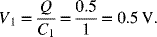
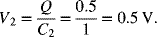
Suppose that you have two capacitors in series, each with a capacitance of 1 farad. What is the total capacitance and what is the potential drop across each capacitor if the total voltage drop across the charged capacitors in series is 1 volt? Repeat this calculation for two capacitors where one of them has a capacitance of 1 F and the other a capacitance of 0.1 F.
SOLUTION:
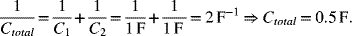
The charge on each capacitor is the same. Therefore, ![]() .
.

Now consider the situation with the two capacitors with different capacitances.
Solution:
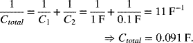
The charge on each capacitor is the same. Therefore, ![]() .
.

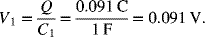
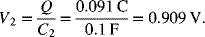
It is clear from these results that the smaller capacitor controls the behavior for the two capacitors in series, leading to a much lower charge capacity for a given voltage than what we calculated above. The majority of the change in voltage is across the smaller capacitor.
Leave a Reply