Having established the energy balance for a closed system, and, from Section 2.3, the work associated with flowing fluids, let us extend these concepts to develop the energy balance for a steady-state flow system. The term steady-state means the following:
1. All state properties throughout the system are invariant with respect to time. The properties may vary with respect to position within the system.
2. The system has constant mass, that is, the total inlet mass flow rate equals the total outlet mass flow rates, and all flow rates are invariant with respect to time.
3. The center of mass for the system is fixed in space. (This restriction is not strictly required, but will be used throughout this text.)
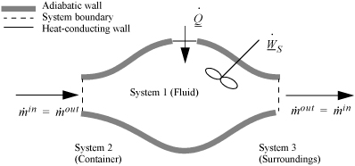
To begin, we write the balance in words, by adding flow to our previous closed-system balance. There are only three ways the surroundings can interact with the system: flow, heat, and work. A schematic of an open steady-state system is shown in Fig. 2.4. In consideration of the types of work encountered in steady-state flow, recognize that expansion/contraction work is rarely involved, so this term is omitted at this preliminary stage. This is because we typically apply the steady-state balance to systems of rigid mechanical equipment, and there is no change in the size of the system. Therefore, the expansion/contraction work term is set to 0.

Figure 2.4. Schematic of a steady-state flow system.
![]() Steady-state flow systems are usually fixed size, so WEC = 0.
Steady-state flow systems are usually fixed size, so WEC = 0.
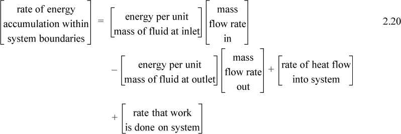
The balance in words becomes time-dependent since we work with flow rates:

Again, we follow the convention that the left-hand side quantifies changes inside our system. Consider the change of energy inside the system boundary given by the left-hand side of the equation. Due to the restrictions placed on the system by steady-state, there is no accumulation of energy within the system boundaries, so the left-hand side of Eqn. 2.20 becomes 0.
As a result,

where heat and work interactions are summed over all boundaries. The flow work from Eqn. 2.7 may be inserted and summed over all inlets and outlets,

and combining flow terms:

Enthalpy
Note that the quantity (U + PV) arises quite naturally in the analysis of flow systems. Flow systems are very common, so it makes sense to define a single symbol that denotes this quantity:
H ≡ U + PV
Thus, we can tabulate precalculated values of H and save steps in calculations for flow systems. We call H the enthalpy.
![]() Enthalpy is a mathematical property defined for convenience in problem solving.
Enthalpy is a mathematical property defined for convenience in problem solving.
The open-system, steady-state balance is then,

![]() Open-system, steady-state balance.
Open-system, steady-state balance.
where the heat and work interactions are summations of the individual heat and work interactions over all boundaries.
Note: Q is positive when the system gains heat energy; W is positive when the system gains work energy; and are always positive; and is positive when the systems gains mass and zero for steady-state flow. Mass may be replaced with moles in a non-reactive system with appropriate care for unit conversion.
Note that the relevant potential and kinetic energies are for the fluid entering and leaving the boundaries, not for the fluid which is inside the system boundaries. When only one inlet and one outlet stream are involved, the steady-state flow rates must be equal, and

![]() Several common ways the steady-state balance can be written.
Several common ways the steady-state balance can be written.
When kinetic and potential energy changes are negligible, we may write

where ΔH = Hout – Hin. We could use molar flow rates for Eqns. 2.24 through 2.26 with the usual care for unit conversions of kinetic and potential energy. For an open steady-state system meeting the restrictions of Eqn. 2.26, we may divide through by the mass flow rate to find

In common usage, it is traditional to relax the convention of keeping only system properties on the left side of the equation. More simply we often write:

Compare Eqns. 2.19 and 2.28. Energy and enthalpy do not come from different energy balances, where the “closed system” balance uses U and WEC and the “open system” balance uses H and Ws. Rather, the terms result from logically simplifying the generalized energy balance shown in the next section.
Comment on Δ Notation
In a closed system we use the Δ symbol to denote the change of a property from initial state to final state. In an open, steady-state system, the left-hand side of the energy balance is zero. Therefore, we frequently write Δ as a shorthand notation to combine the first two flow terms on the right-hand side of the balance, with the symbol meaning “outlet relative to inlet” as shown above. You need to learn to recognize which terms of the energy balance are zero or insignificant for a particular problem, whether a solution is for a closed or open system, and whether the Δ symbol denotes “outlet relative to inlet” or “final relative to initial.”
Understanding Enthalpy and Shaft Work
Consider steady-state, adiabatic, horizontal operation of a pump, turbine, or compressor. It is possible to conceive of a closed packet of fluid as the system while it flows through the equipment. After analyzing the system from this perspective, we can switch to the open-system perspective to gain insight about the relation between open systems and closed systems, energy and enthalpy, and EC work and shaft work. As a bonus, we obtain a handy relation for estimating pump work and the enthalpy of compressed liquids.
In the conception of a closed-system fluid packet, no mass moves across the system boundary. The system, as we have chosen it, does not include a shaft even though it will move past the shaft. If you have trouble seeing this, remember that the system boundaries are defined by the conceived packet of mass. Since the system boundary does not contain the shaft before the packet enters, or after the packet exits, it cannot contain the shaft as it moves through the turbine. The system simply deforms to envelope the shaft. Therefore, all work for this closed system is technically expansion/contraction work; the closed-system expansion/contraction work is composed of the flow work and shaft work that we have seen from the open-system perspective. It is difficult to describe exactly what happens to the system at every point, but we can say something about how it begins and how it ends. This observation leads to what is called an integral method of analysis.
System: closed, adiabatic; Basis: packet of mass m. The kinetic and potential energy changes are negligible:

![]() Note that this derivation neglects kinetic and potential energy changes.
Note that this derivation neglects kinetic and potential energy changes.
Integrating from the inlet (initial) state to the outlet (final) state:
Uout – Uin = WEC
We may change the form of the integral representing work via integration by parts:

We recognize the term PV as representing the work done by the flowing fluid entering and leaving the system; it does not contribute to the work of the device. Therefore, the work interaction with the turbine is the remaining integral, ![]() . Substitution gives,
. Substitution gives,

Switching to the open-system perspective, Eqn. 2.28 gives

Recalling that H = U + PV and comparing the last two equations means Ws = ∫VdP is the work done using the pump, compressor, or turbine as the system. Furthermore, the appearance of the PV contribution in combination with U occurs naturally as part of the integration by parts. Physically, work is always “force times distance.” Though this derivation has been restricted to an adiabatic device, the result is general to devices including heat transfer as we show later in Section 5.7.

Note: The shaft work given by dWS = VdP is distinct from expansion/contraction work, dWEC = PdV. Moreover, both are distinct from flow work, dWflow = PVdm.
![]() Shaft work for a pump or turbine where kinetic and potential energy changes are small.
Shaft work for a pump or turbine where kinetic and potential energy changes are small.
Several practical issues may be considered in light of Eqn. 2.31. First, the work done on the system is negative when the pressure change is negative, as in proceeding through a turbine or expander. This is consistent with our sign convention. Second, when considering gas flow, the integration may seem daunting if an ideal gas is not involved because of the complicated manner that V changes with T and P. Rather, for gases, we can frequently work with the enthalpy for a given state change. The enthalpy values for a state change read from a table or chart lead to Ws directly using Eqn. 2.30. For liquids, however, the integral can be evaluated quickly. Volume can often be approximated as constant, especially when Tr < 0.75. In that case, we obtain by integration an equation for estimating pump work:

![]() Shaft work for a liquid pump or turbine where kinetic and potential energy changes are small and Tr < 0.75 so that the fluid is incompressible.
Shaft work for a liquid pump or turbine where kinetic and potential energy changes are small and Tr < 0.75 so that the fluid is incompressible.
Example 2.4. Pump work for compressing H2O
Use Eqn. 2.31 to estimate the work of compressing 20°C H2O from a saturated liquid to 5 and 50 MPa. Compare to the values obtained using the compressed liquid steam tables.
Solution
For H2O, Tr = 0.75 corresponds to 212°C, so we are safe on that count. We can calculate the pump work from Eqn. 2.31, reading Psat = 0.00234 MPa and VL = 1.002 cm3/g from the saturation tables at 20°C:
⇒ ΔH ≈ VLΔP = 1.002 cm3/g(50 MPa – 0.00234 MPa) = 50.1 MPa-cm3/g for 50 MPa
⇒ ΔH ≈ VLΔP = 1.002 cm3/g(100 MPa – 0.00234 MPa) = 100.2 MPa-cm3/g for 100 MPa
A convenient way of converting units for these calculations is to multiply and divide by the gas constant, noting its different units. This shortcut is especially convenient in this case, e.g.,
ΔH = 50.1 MPa-cm3/g ·(8.314 J/mole-K)/(8.314 MPa-cm3/mole-K) = 50.1 kJ/kg
ΔH = 100.2 MPa-cm3/g ·(8.314 J/mole-K)/(8.314 MPa-cm3/mole-K) = 100.2 kJ/kg
Note that, for water, the change in enthalpy in kJ/kg is roughly equal to the pressure rise in MPa because the specific volume is so close to one and Psat << P. That is really handy.
The saturation enthalpy is read from the saturation tables as 83.95 kJ/kg. The values given in the compressed liquid table (at the end of the steam tables) are 88.6 kJ/kg at 5 MPa and 130 kJ/kg at 50 MPa, corresponding to estimated work values of 4.65 and 46.1 kJ/kg. The estimation error in the computed work is about 7 to 9%, and smaller for lower pressures. This degree of precision is generally satisfactory because the pump work itself is usually small relative to other work and terms (like the work produced by a turbine in a power cycle).
Leave a Reply