Variously called Unit Operations or Mass Transfer Operations, the Separation Processes course deals with physical separations of components and is as critical to a chemical engineering student as the course on reactor design. This course teaches the students how to solve a variety of separation challenges:
• Separation of components from raw materials to obtain a reactor feed of desired purity
• Removal of undesirable contaminants from the raw product stream so that the required product specifications are met
• Recovery of valuable components from the waste stream before it is released to the environment
A student, after this course (or courses) on separations, will be able to make a decision regarding the type of separation process and design the equipment to accomplish the desired separation. Following are the most common separation techniques employed in the chemical industry:
• Distillation: Distillation is the most common technique utilized by the chemical industry for separating miscible components that exist in liquid phase at the given conditions. Distillation is based on differing volatilities (ease of vaporization) of the components of the mixture. For example, a distillation column used in petroleum refining allows us to separate gasoline from diesel (and aviation fuel and other components). Similarly, ethanol-water separation can be effected by distillation. Figure 3.4 shows a general schematic of a distillation column [8].
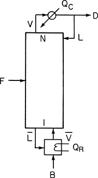
Figure 3.4 Schematic of a distillation column.
Source: Wankat, P. C., Separation Process Engineering, Third Edition, Prentice Hall, Upper Saddle River, New Jersey, 2012.
Feed F to the column is separated into distillate D and bottoms B. The energy needed for the separation is supplied in the reboiler at the bottom of the column to generate a vapor stream. This vapor stream is contacted with a liquid stream flowing down the column. A condenser located at the top of the column condenses the vapor at the top, returning part of the condensed liquid back to the column. The distillate product at the top is preferentially enriched in the more volatile components of the feed, whereas the bottom product is enriched in the less volatile components. Figure 3.5 shows a system of three distillation columns used for solvent recovery in a chemical plant.
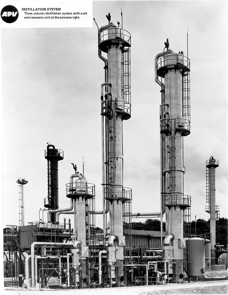
Figure 3.5 A chemical plant with three distillation columns.
Source: Wankat, P. C., Separation Process Engineering, Third Edition, Prentice Hall, Upper Saddle River, New Jersey, 2012.
• Gas absorption/stripping: Both gas absorption and stripping operations involve transferring a component from one phase to another. Removing a contaminant gas (such as H2S or sulfur oxides) from a gas stream (prior to venting the stream to the atmosphere) by absorbing it in an alkaline solution is an example of gas absorption. Stripping is the reverse of absorption wherein a dissolved gas is stripped from a liquid. These operations are based on manipulating the affinity of the target component for one phase over the other. Figure 3.6 shows a schematic of an absorber-stripper system.
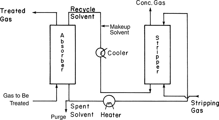
Figure 3.6 Absorber-stripper system.
Source: Wankat, P. C., Separation Process Engineering, Third Edition, Prentice Hall, Upper Saddle River, New Jersey, 2012.
The gas to be treated for the removal of a component is fed at the bottom of the absorber, where it is contacted with a solvent that preferentially dissolves the component. Solvent needed for absorption is regenerated in the stripping column, where the solvent exiting the absorption column that is enriched in the component is contacted with the stripping gas. The stripping column operates at a higher temperature; as a result, the component dissolved in the solvent is transferred to the gas phase.
• Liquid-liquid extraction: A liquid stream is often purified by transferring the impurity to another liquid stream that is immiscible with the feed stream. As with absorption/stripping, manipulating operating conditions allows an engineer to change the affinity of the component of interest. Typically, but not always, one liquid stream is aqueous while the other one is organic. Figure 3.7 shows a conceptual schematic of separation using liquid-liquid extraction using two different contacting devices.
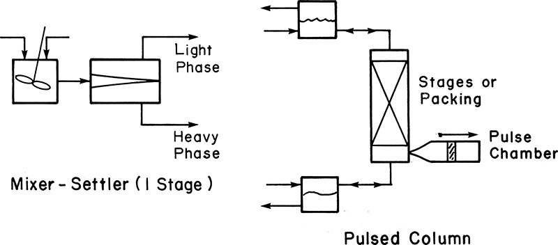
Figure 3.7 Liquid-liquid extraction.
Source: Wankat, P. C., Separation Process Engineering, Third Edition, Prentice Hall, Upper Saddle River, New Jersey, 2012.
In the mixer-settler unit shown on the left, the two immiscible phases are stirred together to promote mixing and transfer of the component of interest. The two phases are separated in the settler unit under the influence of gravity, taking advantage of the density differences. The light and dense phases are removed from different locations in the settler unit. The mixing of phases and the resultant transfer of the component is accomplished by providing a contact surface by means of a packing or stages in a pulsed column. Pulsing the column results in regeneration of surface, promoting the transfer of the component. The phases are separated, as shown in the figure.
• Adsorption: A component is removed from the fluid (gas or liquid) phase by contacting the fluid with a solid. The component is preferentially sorbed to the surface of the solid and essentially removed from the fluid. The principle of the pressure-swing adsorption cycle used for clean-up of an impurity containing gas is shown in Figure 3.8.
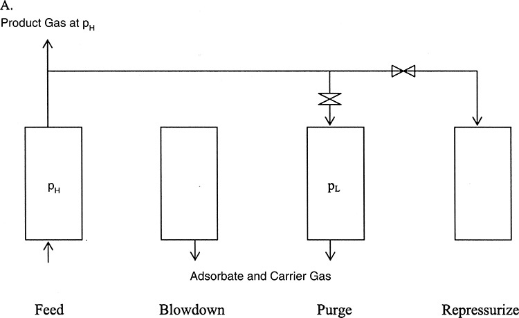
Figure 3.8 Principle of pressure-swing adsorption.
Source: Wankat, P. C., Separation Process Engineering, Third Edition, Prentice Hall, Upper Saddle River, New Jersey, 2012.
The gas containing the impurity is contacted with the adsorbent in a column at high pressure. The adsorbent preferentially sorbs the impurity removing it from the gas, which is collected at the product gas at high pressures (PH). The adsorption column operates in a batch mode; that is, the adsorbent gets progressively saturated with the impurity, losing the ability to clean the gas. At this point, the feed gas flow is stopped, and the column pressure lowered. The third stage consists of purging the column at this low pressure (PL), where the impurity picked by the adsorbent is desorbed or removed, regenerating the column capacity. The last stage is repressurizing the column to high pressure in order to repeat the cycle.
• Evaporation and drying: A stream dilute with respect to a solute is often subjected to evaporation for concentration. For example, a dilute caustic solution is the first product in the caustic soda (NaOH) manufacture. Progressively concentrated solutions (50%, 70%, etc.) are obtained through evaporation. Drying involves continuing this solvent removal to its extreme limit, leaving behind only the pure solute. The solvent can be aqueous (as in the majority of these operations) or organic. These operations consume significant amounts of energy, and an improperly designed evaporator or dryer can impact the plant economics adversely.
• Membrane separations: Figure 3.9 illustrates the principle of separations using membranes. Membranes are semipermeable barriers between two phases, and the separation of a mixture is based on the preferential transfer of one or more of the components across this barrier.

Figure 3.9 Separation using membranes.
Source: Wankat, P. C., Separation Process Engineering, Third Edition, Prentice Hall, Upper Saddle River, New Jersey, 2012.
The schematic on the left shows a crossflow unit where the component transferring across the membrane is swept from the system using a carrier gas. The components not diffusing across exit the unit as retentate. The schematic on the right in Figure 3.9 shows a hollow fiber membrane unit, where permeate diffuses across the tube walls from the feed-retentate stream flowing inside the tubes. Important applications of membrane separations include oxygen-nitrogen separation and desalination.
Several other important separation processes—ion exchange, electrochemical separations, crystallization, and so on—are also studied in this course. The generalized concepts covered in the course provide the foundation for a chemical engineer to design and operate a separation scheme for any mixture.
Leave a Reply