Ordinary Vapor Compression Cycle
The Carnot cycle is not practical for refrigeration for the same reasons as discussed for power production. Therefore, most refrigerators operate on the ordinary vapor-compression (OVC) cycle, shown in Fig. 5.8.

Figure 5.8. OVC refrigeration cycle process schematic and T-S diagram.
![]() The ordinary vapor compression cycle is the most common refrigeration cycle.
The ordinary vapor compression cycle is the most common refrigeration cycle.
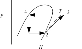
As with the Rankine cycle, we make some simplifications that would have to be reevaluated in a detailed engineering design. Again, we neglect pressure losses in piping. We assume that the vapor is saturated at the inlet to the compressor, and that the outlet of the condenser is saturated liquid. Thus, saturated vapor enters the compressor and exits heated above the condenser temperature, then cools in the condenser until it condenses to a saturated liquid. In the cyclic process, the saturated liquid is passed through a throttle valve at constant enthalpy and exits as a two-phase mixture. The evaporator is assumed to be isothermal, and accepts heat at the colder temperature to complete the vaporization. The OVC cycle is often characterized using a P-H diagram as shown in Fig. 5.9.

Figure 5.9. OVC refrigeration cycle plotted on the more commonly used P-H diagram. State numbers correspond to Fig. 5.8.
The COP can be related to the conditions of the process streams.

![]() COP for ordinary vapor compression cycle.
COP for ordinary vapor compression cycle.
Example 5.4. Refrigeration by vapor compression cycle
An industrial freezer room is to be maintained at –15°C by a cooling unit utilizing refrigerant R134a as the working fluid. The evaporator coils should be maintained at –20°C to ensure efficient heat transfer. Cooling water is available at 10°C from an on-site water well and can be warmed to 25°C in the condenser. The refrigerant temperature exiting the condenser is to be 30°C. The cooling capacity of the freezer unit is to be 120,000 BTU/h (126,500 kJ/h); 12,650 kJ/h is known as one ton of refrigeration because it is approximately the cooling rate (cooling duty) required to freeze one ton of water at 0°C to one ton of ice at 0°C in 24 h. So this refrigerator represents a 10 ton refrigerator. As a common frame of reference, typical home air conditioners are about 2–3 tons, but they typically weigh less than 100 kg. Calculate the COP and recirculation rate (except part (a)) for the industrial freezer in the following cases:
a. Carnot cycle.
b. Ordinary vapor compression cycle with a reversible compressor.
c. Vapor compression cycle with the throttle valve replaced with an expander.
d. Ordinary vapor compression cycle for which compressor is 80% efficient.
![]() 12,650 kJ/h is known as a ton of refrigeration capacity.
12,650 kJ/h is known as a ton of refrigeration capacity.
Solution
We will refer to Fig. 5.8 for identifying state by number. The operating temperatures of the refrigeration unit will be

a. Carnot cycle
Note that T3 will be higher than T4, but we use the condenser outlet T4 as the benchmark temperature.

b. Ordinary VC cycle with reversible compressor
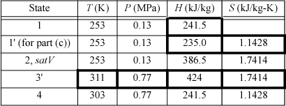
We will create a table to summarize results. Values determined from balances are shown in boldfaced table cells. Other valves are from the R-134a chart in Appendix E. State 2 is a convenient place to start since it is a saturated vapor and the temperature is known. T2 = –20°C, from the chart, H2satV = 386.5 kJ/kg and S2satV = 1.7414 kJ/kg-K. The condenser outlet (state 4) is taken as saturated liquid at 30°C, so the pressure of the condenser will be P4sat (30°C) = 0.77 MPa, and H4 = 241.5 kJ/kg, S4 = 1.1428 kJ/kg-K. Because the throttle valve is isenthalpic (Section 2.13), H1 = H4.

The compressor calculation has already been performed in Example 4.17 on page 174. If the process is reversible, the entropy at state 3′ will be the same as S2. Finding H3′ from S3′ = 1.7414 kJ/kg-K and P3 = 0.77 MPa, using the chart, H3′ = 424 kJ/kg. Note that the pressure in the condenser, not the condenser temperature, fixes the endpoint on the isentropic line from the saturated vapor.

The required circulation rate is

c. VC cycle with turbine expansion
The throttle valve will be replaced by a reversible expander. Therefore, S1′ = S4 = 1.1428 kJ/kg-K. The saturation values at 253 K are SsatL = 0.8994 kJ/kg-K and SsatV = 1.7414 kJ/kg-K; therefore, S1′ = 1.1428 = q’·1.7414 + (1 – q’)0.8994, which gives q’ = 0.289.
Then, using the saturated enthalpy values and the quality, H1′ = 235.0 kJ/kg. In order to calculate the COP, we must recognize that we are able to recover some work from the expander, given by H1′ – H4.

The increase in COP requires a significant increase in equipment complexity and cost, since a two-phase expander would probably have a short life due to erosion of turbine blades by droplets.
d. Like (b) but with irreversible compressor
States 1, 2, and 4 are the same as in (b). The irreversibility simply changes state 3.

Refrigerant choice is dictated by several factors:
1. Environmental impact (Freon R-12 depletes ozone and has been phased out; Freon R-22 is being phased out). HFO1234yf is beginning to supersede R134a.
2. Vapor pressure ~ atmospheric at Tevap. Consequently, the driving force for leakage will be small, but an evaporator pressure slightly above atmospheric pressure is desirable to avoid air leaking into the cycle.
3. Vapor pressure not too high at TH so that the operating pressure is not too high; high pressure increases compressor and equipment costs.
4. High heat of vaporization per unit mass.
5. Small CP/CV of vapor to minimize temperature rise and work of compressor.
6. High heat transfer coefficient in vapor and liquid.
Flash Chamber (Economizer) Intercooling
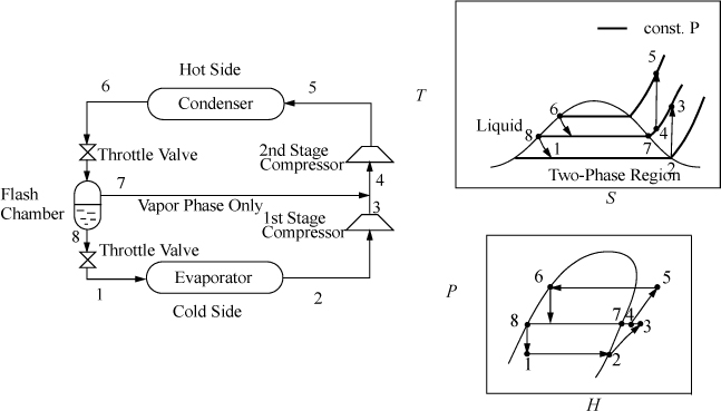
When the temperature difference between the condenser and evaporator is increased, the compressor must span larger pressure ranges. If the compression ratio (Pout/Pin) becomes too large, interstage cooling can be used to increase efficiency. Because the process temperatures are usually below cooling water temperatures, a portion of the condensed refrigerant stream can be flashed to provide the interstage cooling, as shown in Fig. 5.10. The interstage cooler is sometimes called an economizer. The economizer is considered adiabatic unless otherwise specified, and serves to disengage the liquid and vapor exiting the inlet valve. The quality out of the inlet valve is equal to ![]() .
.

Figure 5.10. Flash chamber intercooling.
![]() Flash chamber intercooling is a common method of increasing COP.
Flash chamber intercooling is a common method of increasing COP.
Cascade Refrigeration
![]() Cascade refrigeration is used to reach cryogenic temperatures.
Cascade refrigeration is used to reach cryogenic temperatures.
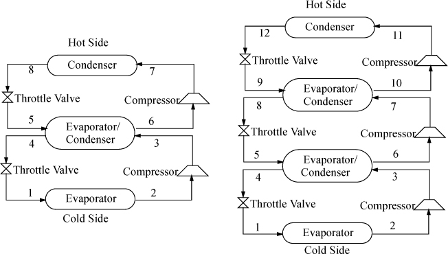
In order to span extremely large temperature ranges, a single refrigerant becomes impractical, because the compression ratio (Pout/Pin) becomes too high and the COP decreases. A typical guideline is that the compression ratio should not be higher than about 8. Therefore, to span extremely large ranges, binary vapor cycles or cascade vapor cycles are used. In a binary cycle, a refrigerant with a normal boiling point below the coldest temperature is used on the cold cycle, and a refrigerant that condenses at a moderate pressure is used on the hot cycle. The two cycles are coupled at the condenser of the cold cycle and the evaporator of the hot cycle as shown in Fig. 5.11. Because the heat of vaporization is coupled to the saturation temperature for any refrigerant, usually the operating temperatures are selected, and the circulation rates are determined for each cycle. Certainly, there are many variables to optimize in a process design of this type. For extremely large ranges, such as for cryogenic processing of liquefied gases, cascade refrigeration can be used with multiple cycles. For example, for the liquefaction of natural gas, the three cycles might be ammonia, ethylene, and methane. Note that the evaporator in each cycle must be colder than the condenser of the cycle below to ensure heat is transferred in the correct direction.

Figure 5.11. Binary cycle (left) and three-cycle cascade (right) refrigeration cycles. The refrigerants do not mix in the evaporator/condensers.
Leave a Reply