A typical reactor design problem for batch reactors involves determination of the batch time needed for producing the specified quantity of the product. This batch time is obtained by separating the variables and integrating equation 9.4 as follows:

Here, Ni0 are the initial moles of i. Many of the batch reactors operate under constant volume conditions; that is, the volume of the reactor is fixed. In this case, equation 9.6 can be expressed conveniently in terms of concentrations, since Ni = V·Ci for a well-mixed reactor and the rate ri is a function of concentrations of the species involved in the reaction. For the reaction shown earlier (A + B → R + S), the batch time can be expressed in terms of concentration of A as follows:

The denominator is the rate of disappearance of A (−rA), which is a function of the concentration of A and temperature. The negative sign signifies that A is a reactant that is consumed in the reaction, as discussed in section 9.1.1. CA0 and CA are the concentrations of A at the beginning and the end of the reaction. The specific form of the function depends on the rate parameters describing the intrinsic kinetics of the reaction. For a reaction that is first order with respect to A—that is, −rA= f(CA, T) = k·CA—integration of equation 9.7 yields the following:

The result shown in equation 9.8 is based on the assumption that the reaction is conducted isothermally; that is, the temperature remains constant, and hence the rate constant does not vary with time. For adiabatic and other nonisothermal modes of operation, numerical integration of equation 9.7 may be needed for obtaining the batch time.
Equation 9.5 can be used for the design of a CSTR/MFR, as an assumption implicit in equation 9.5 (and the original equation 9.1) is that the contents of the reactor are uniform, which holds true for the CSTR/MFR. The reactor volume can then be determined using equation 9.9 [4]:

If the reaction does not involve any change in volume, then equation 9.9 can be simplified by writing the molar flow rates as products of the volumetric flow rate and concentration (FA = v · CA, v being the volumetric flow rate) to obtain equation 9.10:

In this equation, ![]() is the mean residence time of the fluid in the reactor. Depending on the nature of the functional dependence of the rate on concentration, an algebraic or transcendental equation in CA is obtained as the design equation for the CSTR [4].
is the mean residence time of the fluid in the reactor. Depending on the nature of the functional dependence of the rate on concentration, an algebraic or transcendental equation in CA is obtained as the design equation for the CSTR [4].
Equation 9.5 cannot be used directly for the design of PFR or PBR, as conditions in these reactors show spatial variation. For these reactors, the component material balances are written over a differential element of the reactor, and the reactor volume for PFR is obtained by the integration of the resulting differential equation as shown by equations 9.11 and 9.12, respectively:


For a PBR, the rate expression is usually written in terms of catalyst mass, and the equivalent differential and integral forms of the previous two equations are as follows:


Here, ![]() indicates that the rate is expressed in terms of per unit mass rather than per unit volume.
indicates that the rate is expressed in terms of per unit mass rather than per unit volume.
The molar flow rates can be substituted by the products of concentrations and volumetric flow rates, and when the reaction does not involve any volume change, equation 9.12 for the PFR simplifies as follows:

Here, ![]() is the mean residence time in the PFR.
is the mean residence time in the PFR.
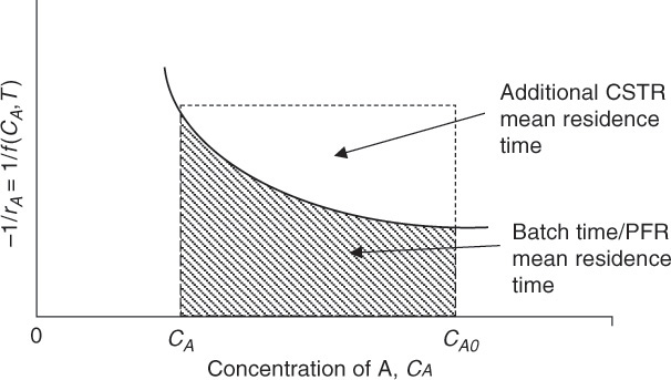
The similarity and equivalence between a batch reactor and a PFR should readily become apparent by a comparison of equations 9.7 and 9.15. The batch time in a batch reactor is equivalent to the mean residence time in the PFR. As with the batch reactor, equation 9.15 may be integrated analytically for isothermal reactors and other situations, while numerical and other techniques may be needed for nonisothermal operations and complex rate equations. A graphical representation of equations 9.7, 9.10, and 9.15 is shown in Figure 9.3.

Figure 9.3 Graphical interpretation of equations 9.7, 9.10, and 9.15. CSTR, continuous stirred tank reactor; PFR, plug flow reactor.
The batch time or the mean residence time for the PFR is represented by the area under the curve bound by the final and initial concentrations. The mean residence time for the CSTR is the area of the rectangle formed by the sides of the length (CA0 − CA) and −1/rA evaluated at CA. This area includes the area under the curve as well as the area above the curve bound by the dashed lines. It can be seen that, in this instance, the mean residence time needed for the CSTR operation is greater than the mean residence time needed in the PFR. This translates into a higher volume requirement for the CSTR for the same processing rate, and it may be advantageous to choose a PFR to conduct the reaction. Figure 9.3 is a type of Levenspiel plot used to obtain the reactor volume, residence time, and batch time for the reactors [5]. A more common representation of the Levenspiel plot involves a graph of FA0/(−rA) as a function of conversion of A.
Leave a Reply