Two modifications of the Rankine cycle are in common use to improve the efficiency. A Rankine cycle with reheat increases the boiler pressure but keeps the maximum temperature approximately the same. The maximum temperatures of the boilers are limited by corrosion concerns. This modification uses a two-stage turbine with reheat in-between. An illustration of the modified cycle is shown in Fig. 5.3. Crudely, adding multiple stages with reheat leads to the maximum temperature being applied as much as possible, while avoiding extremely wet steam during expansion. This moves the process efficiency in the direction of a Carnot cycle. The implication of this modification is shown in Example 5.2.

Figure 5.3. Rankine cycle with reheat.
Example 5.2. A Rankine cycle with reheat
Consider a modification of Example 5.1. If we limit the process to a 500°C boiler/superheater with reheat, we can develop a new cycle to investigate an improvement in efficiency and circulation rate. Let us operate a cycle utilizing two reversible turbines with ηE = 0.85 and a pump with ηC = 0.8. Let the feed to the first turbine be steam at 500°C and 6 MPa. Let the feed to the second stage be 1.4 MPa and 500°C (the same as Example 5.1). Determine the improvement in efficiency and circulation rate relative to Example 5.1.
Solution
Refer to Fig. 5.3 for stream numbers. First, let us find state 3. The inlet state values are entered in the table. P4 = P5 because we neglect the heat exchanger pressure drop. Upon expansion through the first reversible turbine, we look at the SsatV at 1.4 MPa and find it lower that S4’. Therefore, the reversible state is superheated. Using {S,P} to find H,

Correcting for efficiency,
ΔHI = WS, I = 0.85(3001.2 – 3423.1) = 0.85(–421.9) = –358.6 kJ/kg
H4 = 3423.1 – 358.6 = 3064.5 kJ/kg

State 5 was used in Example 5.1 (as state 3). Solving the energy balance for the reheater,
Qreheat = (H5 – H4) = 3474.8 – 3064.5 = 410.3 kJ/kg
Turbine II was analyzed in Example 5.1. We found WS,II = –959.0 kJ/kg and the total work output is WS,turbines = (–358.6 –959.0) = –1317.6 kJ/kg. The pump must raise the pressure to 6 MPa. Using Eqn. 2.61, and correcting for efficiency,

State 7 is the same as state 5 in Example 5.1 and has been tabulated in the property table. H8 = H7 + WS,pump = 191.8 + 7.6 = 199.4 kJ/kg. The net work is thus
WS, net = –1317.6 + 7.6 = –1310 kJ/kg
The heat for the boiler/superheater is given by Qb/s = H3 – H8 = 3423.1 – 199.4 = 3223.7 kJ/kg.
The thermal efficiency is

The efficiency has improved by ![]() , and the circulation rate has been decreased by 27%.
, and the circulation rate has been decreased by 27%.
![]() Reheat improves thermal efficiency.
Reheat improves thermal efficiency.
One variation of the Rankine cycle is for cogeneration as illustrated in Fig. 5.4. Most chemical plants need process steam for heating distillation columns or reactors as well as electrical energy. Therefore, they use steam at intermediate pressures, depending on the need, and circulate the condensate back to the boiler. Another very common modification of the Rankine cycle is a regenerative cycle using feedwater preheaters. A portion of high-pressure steam is used to preheat the water as it passes from the pump back to the boiler. A schematic of such a process is shown in Fig. 5.5 using closed feedwater preheaters. The economic favorability increases until about five preheaters are used, then the improvements are not worth the extra cost. Three preheaters are more common. As the condensate from each preheater enters the next preheater, it throttles through a valve to the next lower pressure and partially or totally vaporizes as it throttles. It is also common to withdraw some steam from turbine outlets for process use and heating. Often in actual processes, open feedwater preheaters are used. In an open feedwater preheater, all of the incoming streams mix. The advantage of this preheater is that dissolved oxygen in the returning condensate can be removed by heating, and if provision is made to vent the non-condensables from the open feedwater preheater, it may serve as a deaerator to remove dissolved air before feeding the boiler. A system with an open feedwater preheater is shown in Fig. 5.6. The vent on the open feedwater preheater is typically a small stream and omitted in the schematics and first order calculations. A regenerative Rankine cycle is illustrated in Example 5.3.
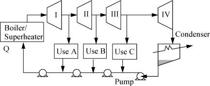
Figure 5.4. Rankine cycle with side draws for process steam. Pumps and/or throttles may be used in returning process steam to the boiler.
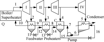
Figure 5.5. Regenerative Rankine cycle using closed feedwater preheaters.
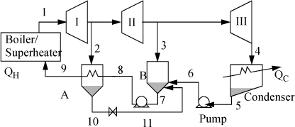
Figure 5.6. Schematic for a system with a closed feedwater preheater, A, and an open feedwater preheater, B.
Example 5.3. Regenerative Rankine cycle
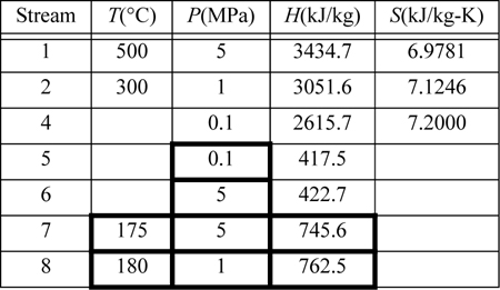
Steam (1) exits a boiler/superheater at 500°C and 5 MPa. A process schematic is shown in Fig. 5.7. The first stage of the turbine exits (2, 3) at 1MPa and the second stage of the turbine exits (4) at 0.1 MPa. A feed preheater is used to exchange heat with a 5°C approach temperature between streams 7 and 8. Find the net power output per kg of flow in stream 1.
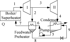
Figure 5.7. Regenerative Rankine cycle for Example 5.3.
Solution
First, note that streams 2 and 8 are on the same side of the feedwater preheater and are thus at the same pressure. Streams 7 and 6 must be at the boiler pressure by similar arguments. And stream 5 must likewise be at the condenser pressure. Stream 8 leaves as saturated liquid at the 1 MPa, thus we find H8 = 762.5 kJ/kg, and T8 = 180°C. Stream 7 is thus at 175°C and 5 MPa. Following Example 2.6 for a compressed liquid, H7 = 741.02kJ/kg + (5–0.893MPa)(1.12cm3/g) = 745.6 kJ/kg. Often, one of the key steps in working a problem involving a regenerative cycle is to solve for the fraction of each flow diverted rather than solving for the individual flow rates.
![]() Solving for flowrate ratios in regenerative cycles can be helpful when the total flowrate is unknown.
Solving for flowrate ratios in regenerative cycles can be helpful when the total flowrate is unknown.
The flow rates of streams 7, 6, and 5 are equal to the flow rate of stream 1, and we may write the energy balance around the feedwater preheater using the mass flow rate of stream 1 together with the mass flow rate of stream 2, ![]() . Dividing by
. Dividing by ![]() and substituting values gives
and substituting values gives ![]() , and
, and ![]() .
.
The net work is given by ![]() , and on the basis of one kg from the boiler/superheater,
, and on the basis of one kg from the boiler/superheater, ![]() , and using enthalpies to calculate the work of each turbine,
, and using enthalpies to calculate the work of each turbine,

Referring to the tabulated values,

When you consider all combinations of reheat and regeneration, it is clear that the number of configurations of turbine stages and heat exchangers is nearly endless. Practically speaking, one approaches a point of diminishing returns with each added complexity. The best alternative may depend on details of the specific application. Broadly speaking, Example 5.2 shows a clear 24% gain in thermal efficiency by using reheat. Example 5.3 is not at the same conditions as Example 5.1, but we can quickly estimate the thermal efficiency at the same conditions as ηθ = (3435 – 2617)/(3435 – 422) = 0.271, so regeneration alone offers just a 3% gain. A dedicated electric power facility would definitely want to make the most of every gain, but a small power generator for a chemical facility in an isolated rural area might be subject to other constraints. For example, the need for medium pressure steam to run distillation columns might dictate the pressure for the intermediate stage and a similar need for building heat could dictate a lower temperature requirement. In the final analysis, it is up to the engineer to devise the best solution by adapting these examples and general observations to any particular situation.
Leave a Reply