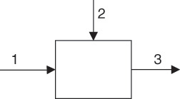
Consider an arbitrary process represented by the block flow diagram shown in Figure 6.1. The process unit has two influent flows (streams 1 and 2) feeding into a tank and one effluent flow (stream 3) leaving the tank.

Figure 6.1 A simple process unit.
Physically, the material being fed to the process must either accumulate in it or exit the system. The principle of conservation of mass dictates that the total mass fed to the system must equal the sum of the mass exiting the system and the mass accumulating in the system [2, 3]:

If ![]() ,
, ![]() , and
, and ![]() are the mass flow rates of the three streams, and mS is the total mass in the process unit,2 then
are the mass flow rates of the three streams, and mS is the total mass in the process unit,2 then
2. By convention, a variable with a dot placed on top indicates a rate, so while m represents the mass (g, kg, and so on), ![]() represents the mass rate (g/s, kg/h, and so on).
represents the mass rate (g/s, kg/h, and so on).

Equation 6.1 is the mathematical representation of the overall material balance for the process. If the rate at which material is taken out of the system, ![]() , is smaller than the rate at which material is being fed to the system,
, is smaller than the rate at which material is being fed to the system, ![]() , material will accumulate in the process, increasing the system mass mS, as would be the case during process start-up. On the other hand, if
, material will accumulate in the process, increasing the system mass mS, as would be the case during process start-up. On the other hand, if ![]() is greater than
is greater than ![]() —that is, material is removed at a faster rate from the process than being fed—then mS will decrease with time, as in the case of draining a tank. Generalizing for multiple input and output streams, the overall material balance equation is as follows:
—that is, material is removed at a faster rate from the process than being fed—then mS will decrease with time, as in the case of draining a tank. Generalizing for multiple input and output streams, the overall material balance equation is as follows:

Here, ![]() and
and ![]() represent the mass flow rates of the ith inlet and jth outlet streams. As mentioned previously, a large number of chemical processes operate at steady state, meaning that the conditions are invariant with respect to time. The overall material balance for such steady-state processes is then simplified to equation 6.3.
represent the mass flow rates of the ith inlet and jth outlet streams. As mentioned previously, a large number of chemical processes operate at steady state, meaning that the conditions are invariant with respect to time. The overall material balance for such steady-state processes is then simplified to equation 6.3.

The overall balance clearly serves a valuable purpose in material accounting. The discrepancy between mass inflow and outflow may be used to estimate atmospheric fugitive emissions and leakages and to identify malfunctioning process equipment.
Leave a Reply