The incompleteness of the desired reaction and the occurrence of undesired side reaction introduced additional levels of complexity in the simple combustion process previously described. By now, readers should have developed a sense of the enormity of computational tasks for a chemical process plant, considering that a chemical process typically has a large number of interconnected process units handling complex streams. An example of such computations involving multiple units is presented in Example 6.4.1. The example deals with a (considerably) simplified ammonia (NH3) synthesis process.
EXAMPLE 6.4.1 AIR, METHANE, AND STEAM REQUIREMENT FOR AMMONIA SYNTHESIS
What are the quantities of the air, CH4, and steam needed to produce 1000 tpd of NH3?
Solution
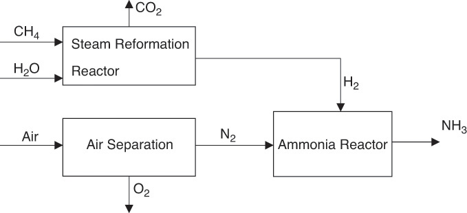
NH3 synthesis requires N2 and hydrogen (H2). As mentioned in previous chapters, H2 needed for the process is typically obtained by steam reforming of CH4, hence the need for CH4 and steam. N2 needed is obtained from air. We will assume in this example that N2 is obtained by cryogenic distillation of air. The simplified block diagram of the process is shown in Figure 6.9.

Figure 6.9 Simplified block flow diagram of ammonia synthesis process.
Typically, the approach to solving the material balance computational problems involves first defining a basis for computation. The NH3 production capacity of the reactor stated in the problem is 1000 tpd. However, computations are rarely based on such stated numbers. Typically, the problem is solved assuming a molar basis—in this case, the basis is 1 mole of NH3 produced. The stepwise procedure beginning with this basis follows:
1. Compute the N2 and H2 requirements from the reaction stoichiometry (0.5N2 + 1.5H2 → NH3). Here the molar stoichiometric ratios are H2/NH3 = 1.5; N2/NH3 = 0.5. Therefore, the inlet to the reactor consists of 0.5 moles of N2 and 1.5 moles of H2.
2. Obtain the 0.5 moles of N2 from the air separation unit, as shown in the figure. The total air fed to the unit must be 0.5/0.79 = 0.63 moles. Assuming that the air is simply a mixture of O2 and N2, this results in 0.13 moles of O2 being fed to the separation unit, and these are recovered as pure O2 product.
3. Obtain the 1.5 moles of H2 needed for the process from the steam reforming process. The steam reforming and water-gas shift reactions follow:
Steam reforming: CH4 + H2O → CO + 3H2
Water-gas shift: CO + H2O → CO2 + H2
Overall: CH4 + 2H2O → CO2 + 4H2
The overall stoichiometry of the process indicates that 4 moles of H2 are obtained from 1 mole of CH4 and 2 moles of H2O (steam). Hence, the molar flow rates of CH4 and H2O needed are 1.5/4 and 1.5/2, that is, 0.375 and 0.75 moles, respectively. The process also generates 0.375 moles of CO2.
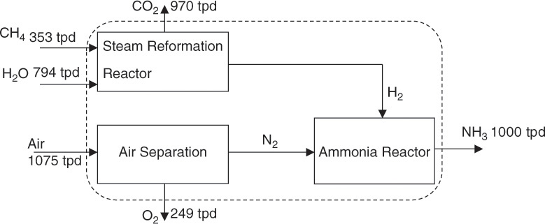
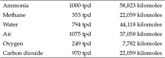
4. Once the quantities of all the species have been determined on the chosen basis (1 mole of NH3 produced), calculate the actual quantities for the specified capacity of 1000 tpd of NH3—that is, 58,823 kilomoles of NH3—by simply scaling by the mole ratio (58,823 kilomoles/mole), as shown here and in Figure 6.10:

Figure 6.10 Material flows for ammonia synthesis process.

Based on these numbers, the total mass flow into the system (CH4, air, H2O) is 2,222 tpd, and the total outflow from the system (NH3, O2, CO2) is 2,219 tpd. This discrepancy is due to rounding errors rather than any computational or analysis error.
Material flows for N2 and H2 are not shown in Figure 6.10. These calculations are left to the reader, who is also encouraged to confirm the material balance for each individual unit of the process. The dashed line in Figure 6.10 forms an envelope establishing a system boundary. The inlet and outlet mass flow rates crossing the boundary are balanced as shown. Similar envelopes can be drawn around any part of the process, and material balance for that part verified.
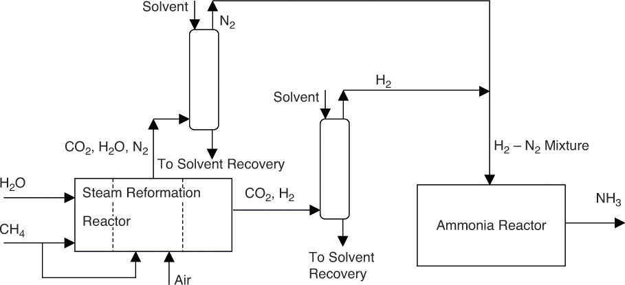
The steam reforming reaction is highly endothermic, and required elevated temperatures are achieved through the combustion of CH4 itself. When stoichiometric quantity of air is used for the combustion of CH4, CO2 and H2O (and other impurities) can be removed from the exhaust gases, yielding N2 needed for NH3 synthesis [5]. CO2 and H2O removal is typically carried out by absorption in a solvent, usually monoethanolamine [6]. The schematic flowsheet for this mode of operation is shown in Figure 6.11.

Figure 6.11 Ammonia synthesis process schematic with details of separation.
It should be noted that the steam reforming reaction also produces a stream containing CO2, the other major component of that stream being H2. CO2 removal from this stream also requires separation operations such as absorption and membrane separation that were not shown in Figures 6.9 and 6.10.
The dashed lines in the steam reformation reactor in Figure 6.11 indicate that the two streams—the process stream composed of CH4 and steam, and the combustion gas stream consisting of CH4 and air—are physically isolated from each other. Typically, the process stream flows through tubes arranged inside a combustion chamber. The tubes are packed with the appropriate catalyst needed for the reaction.
The process shown in Figure 6.11 is considerably more complicated than the one shown in Figure 6.9. However, the actual process is even more complex, with several more separation units needed for removals/recoveries of other components and recycle streams for the reactor and other units. The principles of material balances for such complex processes and techniques for performing the computations are taught in the Material and Energy Balance course taken in the sophomore year of the chemical engineering program, as explained in Chapter 3.
Leave a Reply