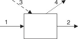
Consider an arbitrary process represented by the block flow diagram shown in Figure 7.1.

Figure 7.1 Energy balance on a process unit; Streams: 1—Inlet, 2—Outlet, 3—Heat, 4—Work.
This diagram is similar to the one shown in Figure 6.1 for the material balance, except for the following important differences: First, the streams represent energy flows rather than material flows. The solid lines indicate energy flows that accompany material flows into and out of the process unit. (All inlet/outlet energy flows that accompany the material flows are combined into one stream each.) Second, the system representing the process unit can exchange energy with the surroundings through either work or heat.2 These streams are shown by dotted (work) and dashed (heat) lines, respectively.
2. The detailed discussion of concepts of work and heat is typically covered in the engineering thermodynamics courses and is not attempted here. Heat is simply understood to be the form of energy transferred from an object at a higher temperature to another at a lower temperature.
It is, of course, not necessary that there be an exchange of heat between the system and the surroundings. Similarly, the system may or may not do any work (or have work done on it). In the most general case, the application of the conservation of energy principle to this system leads to the following energy balance equation:
Rate of accumulation of energy in system =
Rate of energy flow in with material flows
– Rate of energy flow out with material flows
+ Rate of heat input to the system
– Rate of work done by the system
Note that the direction of heat and work streams will change depending on whether heat is added to or removed from the system, and work is done by the system or done on the system. Physically, the material being fed to the process must either accumulate in it or exit the system, as discussed in Chapter 6, “Material Balance Computations.”
If ![]() and
and ![]() represent the rates of energy flowing in and out respectively along with the material flows,
represent the rates of energy flowing in and out respectively along with the material flows, ![]() is the rate of heat input, and is the rate of work done by the system, then we have the following:
is the rate of heat input, and is the rate of work done by the system, then we have the following:

Here, E is the total energy of the system.
Equation 7.1 is the mathematical representation of the overall energy balance for the system or process. If the system is operating at steady state, then we have the following:

There are several situations in chemical processes where no heat exchange is involved and internal energy changes are negligible. The energy balance then reduces to a mechanical energy balance, typically encountered in fluid flow situations and used for determining power requirements for transferring material from one point to another. On the other hand, the changes in mechanical energy are almost invariably insignificant as compared to the changes in internal energy in almost all other process units, and the energy balance simplifies to the following:

In this equation, ![]() is the difference in internal energy between the outlet and inlet energy streams.
is the difference in internal energy between the outlet and inlet energy streams.
Equation 7.3 is useful for performing energy balance computations for steady-state processes. However, the equation is somewhat cumbersome and unwieldy to use and can be simplified further. The conceptual basis for this simplification is as follows:
The work input is typically considered to comprise three components—the flow work, the shaft work (such as that done by a pump or an agitator in a tank), and other work. The flow work terms associated with streams, when combined with the internal energy terms for the streams, yield the enthalpies3 of the streams. Any other type of work excluding the flow and shaft work is lumped together as other work. If the shaft and other work can also be neglected, then the energy balance can be written as follows:
3. Enthalpy (H) is a thermodynamic quantity that is a measure of the heat content of a stream or object: H = U + PV; P is the pressure, V is the volume.

Equation 7.4 is simply stating that the difference between the heat contents of outlet and inlet streams is equal to the heat supplied to the system.
Several processes operate under adiabatic conditions, that is, there is no heat exchange between the system and the surroundings (![]() ). The energy balance for these processes is written as follows:
). The energy balance for these processes is written as follows:

Equations 7.4 and 7.5 provide the framework for the energy balance computations for chemical processes. However, these equations are in terms of enthalpy, a thermodynamic quantity, which cannot be measured and whose absolute value for a substance is unknown. Practical application of energy balances requires expressing the equations in terms of measurable quantities, such as temperature. The next section presents some basic principles related to enthalpy and illustrates how the previous equations are converted into useful forms. The rigorous mathematical development of the simplifying steps is left to the thermodynamics and material and energy balance courses.
Leave a Reply