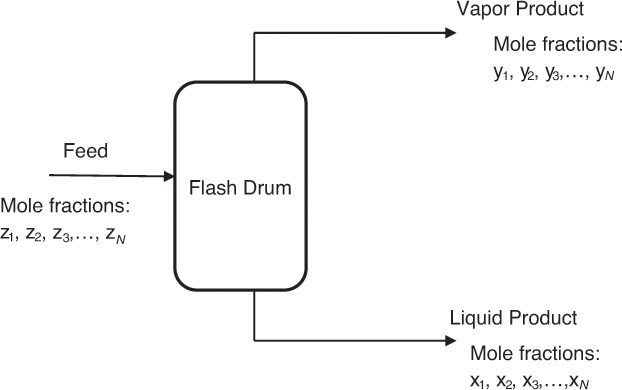
Algebraic equations comprise the most common group of problems in chemical engineering. Linear algebraic equations are algebraic equations in which all the terms are either a constant or a first-order variable [1]. The straight line is represented by a linear algebraic equation. Linear algebraic equations are often encountered in phase equilibrium problems associated with separation processes. Figure 4.1 is a representation of one such separation operation, wherein a high-pressure liquid stream is fed to a flash drum where the system pressure is reduced, resulting in the formation of a vapor and a liquid stream that exit the drum. The compositions of the liquid and the vapor stream depend on the process conditions, and a chemical engineer has to calculate these compositions.

Figure 4.1 Operation of a flash drum.
The governing equations for the system follow:


Equations 4.1 and 4.2 state that the mole fractions of all components, numbering n, in each phase add up to 1. xi and yi represent the mole fractions of component i in the outlet liquid and gas phases, respectively. The mole fractions in the feed stream are denoted by zi. (Typically, x is used to represent the mole fraction when the phase is liquid, and y is used when the phase is gaseous.) These two equations should be intuitively clear, as the mathematical statements of the concept that all fractions of any quantity must add up to the whole. Equation 4.3 is actually a system of n equations relating the mole fraction of a component in the gas phase to the mole fraction of the same component in the liquid phase. Ki is a characteristic constant for component i and is dependent on pressure, temperature, and the nature of the component mixture. Solution of this system of equations allows us to calculate the compositions of the two different phases, which is necessary for designing the separation scheme for the mixture. Each term in the system of equations is linear (variables having power of 1) in x or y.
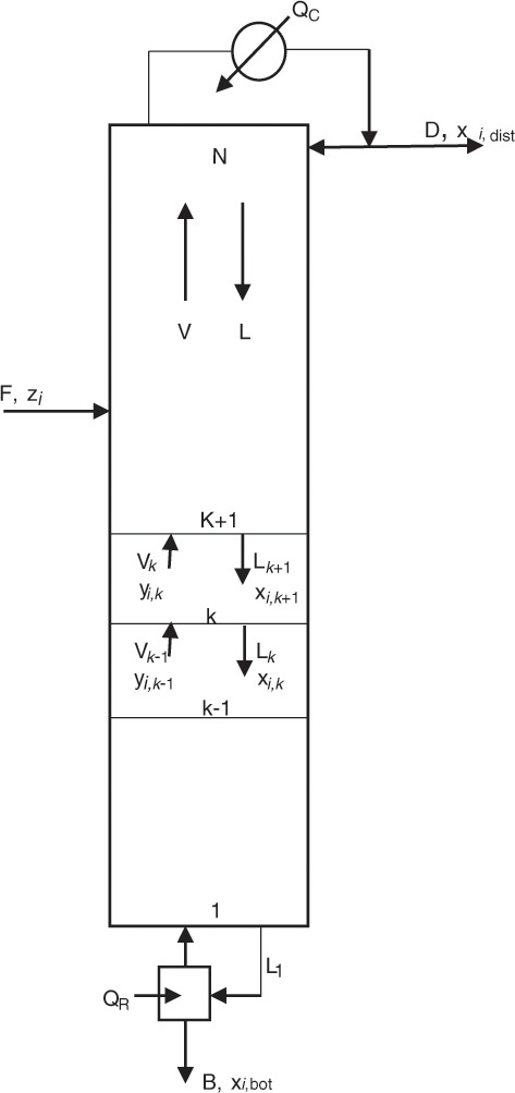
A similar system of equations is used to model a stagewise gas-liquid contactor, such as a distillation column, described in Chapter 3. Figure 4.2 represents a distillation column containing N equilibrium stages [2]; the vapor and liquid inlet and outlet flows can be seen in the figure for stage k.

Figure 4.2 Distillation column—stagewise operation.
Source: Adapted from Wankat, P. C., Separation Process Principles, Third Edition, Prentice Hall, Upper Saddle River, New Jersey, 2012.
The material balances for each component yield the following system of n equations for stage k:

V and L represent the molar flow rates of the vapor and liquid stream, respectively. The subscripts for these flow rates represent the stage from which these flows exit. For example, Vk and Lk are the vapor and liquid flow rates exiting stage k, respectively. Lk+1 is the liquid flow rate exiting stage k + 1 and entering stage k, and Vk−1 is the vapor flow rate exiting stage k − 1 and entering stage k. The mole fractions are doubly subscripted variables, the first subscript representing the component, the second one the stage. Equation 4.4 is the mathematical representation of the steady-state nature of the system for each component: the amount of component i entering the stage through vapor and liquid flows is the same as the amount leaving through the exiting vapor and liquid flows. Each stage is assumed to be an equilibrium stage; that is, the exiting vapor and liquid flows are in equilibrium with each other. This allows us to utilize the equilibrium relationships of the form shown by equation 4.3 to complete the system description. The total number of equations for the entire column is N × n, which can be significantly large depending on the number of components present in the process stream and the number of stages needed to obtain the desired separation.
Algebraic equations encountered in chemical engineering can also be polynomial equations; that is, they can have variable orders greater than one. Equation 4.5 represents a typical polynomial equation of interest to chemical engineers:

This equation is an example of a cubic equation of state, V being the volume of the substance under the given conditions of temperature (T) and pressure (P). Constants a, b, c, and d are functions of the system pressure, temperature, number of moles, and fluid properties. An equation of state represents the relationship between the system temperature, pressure, and volume; the ideal gas law represented by the mathematical expression PV = nRT is the simplest of the equations of state. These equations of state are further used in thermodynamic calculations involving interconversion between energy and work, and phase equilibrium. It is readily apparent that an accurate equation of state is critical for superior process design and performance. Unfortunately, the volumetric behavior of most substances does not conform to the ideal gas law, and more complex equations are needed for accurately describing the P–V–T relationships for these substances. The cubic equations of state represent one of the developments addressing this need for improved accuracy. Equation 4.6 is an example of the cubic equation of state and is called the van der Waals equation [3].

In this equation, a and b are constants characteristic of the substance, and n is the number of moles present in the system.
Several other more complex equations have also been developed, many of them polynomial in nature. A chemical engineering student encounters polynomial equations in practically every subject described in Chapter 3.
Leave a Reply